


Special offers from our partners!

Find Replacement BBQ Parts for 20,308 Models. Repair your BBQ today.

25
W415-0583 / B / 05.23.07
CONVERSION KIT
This conversion kit shall be installed by
a qualifi ed service agency in accordance
with the manufacturer’s instructions and
all applicable codes and requirements
of the authority having jurisdiction. If
the information in these instruction is
not followed exactly, a fi re, explosion
or production of carbon monoxide may
result causing property damage, per-
sonal injury or loss of life. The qualifi ed
service agency is responsible for the
proper installation of this kit. The instal-
lation is not proper and complete until
the operation of the converted appliance
is checked as specifi ed in the owner in-
structions supplied with the kit.
1. “CAUTION” Before proceeding with conversion, the gas
supply must be shut off prior to disconnecting the electric
power.
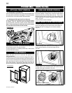
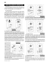
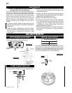
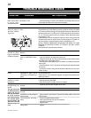
2. Remove the
optional front by
lifting it up and
away from the front
of the fi replace.
(Fig. 1)
3. Remove the
glass door by
pulling the two
latch handles
located along the
top front edge
forward and then
lift the hook out
from the slot in
the door frame,
to release the
top of the door.
Next, pivot the
door forward
until the top
edge of the door
clears the front
of the fi replace.
Grip the sides of
the door & lift the
door out from the
retainer along
the bottom. (Fig.
1)
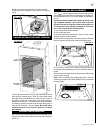
4. Remove the control panel cover. (Fig. 2)
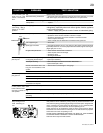
5. Remove the bowl and rockset exposing the pilot
assembly.
PILOT
HOOD
PILOT
INJECTOR
SIT
Fig. 3
Optional Front
Glass Door
Latches
Fig.1
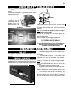
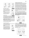
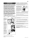
6. Using a deep
9
/
16
” socket wrench, remove the main
burner orifi ce. A
7
/
8
” back-up wrench must be used on the
manifold, located below the housing to ensure that the
aluminium tubing does not twist or kink. Replace the burner
orifi ce supplied using pipe thread compound.
7. Remove the burner hood
from the pilot assembly by
pulling vertically. Use a
5
/
32
” allen key to unscrew
the injector. Replace the
pilot injector with the one
supplied. Replace the pilot
hood onto the assembly
ensuring key position for
proper alignment.
8. Before replacing the burner assembly, adjust the burner
shutter opening to
1
/
2
” for propane and
1
/
16
” for natural gas.
9. Replace and re-secure the burner assembly, ensuring that
the venturi fi ts over the burner orifi ce.
10. To convert the main valve to the desired fuel, follow the
instructions that are supplied with the SIT regulator assembly
kit.
11. The conversion data label must be fi lled out and attached
adjacent to the valve.
12. Turn on the gas supply and check for gas leaks by brushing
on a soap and water solution. Do not use open fl ame.
13. Refer to page 28 for min and max pressures and
instructions for checking proper pressures. Replace the front
portion of the air defl ector and install the logs.
14. Then light the pilot and main burner to ensure that the
gas lines have been purged and that the fi replace is operating
properly at 26,000 BTU’s for both fuels.
15. Re assemble the remaining components & turn on the
electrical supply to the fi replace.
Purge all gas lines with the glass door open.
Assure that a continuous fl ow is at the burner before
closing the door.
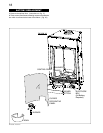
BURNER
CURVED
DECORATIVE
PANEL
BURNER
BOTTOM
BURNER
BASE
S
E
E
-
T
H
R
U
W
I
N
D
O
W
ELECTRODE
BOX
(AA Battery
Required)
CONTROL PANEL
CONTROL PANEL