


Special offers from our partners!

Find Replacement BBQ Parts for 20,308 Models. Repair your BBQ today.

6
W415-0665 / B / 02.11.08
VENTING
For safe and proper operation of the fireplace follow the venting
instruction exactly.
Deviation from the minimum vertical vent length can create
difficulty in burner start-up and/or carboning.
Provide a means for visually checking the vent connection to the
fireplace after the fireplace is installed.
Vent lengths that pass through unheated spaces (attics, garages,
crawl spaces) should be insulated with the insulation wrapped in
a protective sleeve to minimize condensation.
Use only Wolf Steel, Simpson Dura-Vent, Selkirk Direct Temp or
A
merican Metal Amerivent venting components.
Wolf Steel, Simpson Dura-Vent, Selkirk Direct Temp and
A
merican Metal Amerivent venting systems must not be
combined.
Follow the installation procedure provided with the venting
components.
For vent systems that provide seals on the inner exhaust flue,
only the outer air intake joints must be sealed using a red high
temperature silicone (RTV). This same sealant maybe used on
both the inner exhaust and outer intake vent pipe joints of all
other approved vent systems except for the exhaust vent pipe
connection to the fireplace flue collar which must be sealed using
the black high temperature sealant MillPac. A starter adaptor
must be used and may be purchased from the corresponding
supplier:
Supplier 4 / 7
Duravent W175-0053
A
merivent 4DSC-N2
Direct Temp 4DT-AAN
For Simpson Dura-Vent, Selkirk Direct Temp and American Metal
A
merivent, follow the installation procedure found on the website
for your venting supplier:
VENTING SUPPLIER WEBSITE ADDRESS
Simpson Dura-Vent www.duravent.com
Selkirk Direct Temp www.selkirkcorp.com
A
merican Metal Amerivent www.americanmetalproducts.com
When using Napoleon® venting components, use only approved
Wolf Steel Ltd. rigid / flexible vent components with the following
termination kits: wall terminal kit GD222 and GD222R, or 1/12 to
7/12 pitch roof terminal kit GD110, 8/12 to 12/12 roof terminal kit
GD111, flat roof terminal kit GD112 or periscope kit GD201 (for
wall penetration below grade). With flexible venting, in conjunction
with the various terminations, use either the 5 foot vent kit GD220
or the 10 foot vent kit GD330. These vent kits allow for either
horizontal or vertical venting of the fireplace.
The maximum number of allowable 4” vent connections is three
horizontally or vertically (excluding the fireplace and the air
terminal connections).
For optimum flame appearance and fireplace performance, keep
the vent length and number of elbows to a minimum.
Under extreme vent configurations, allow several minutes (5-15)
for the flame to stabilize after ignition.
The air terminal must remain unobstructed at all times. Examine
the air terminal at least once a year to verify that it is unobstructed
and undamaged.
Horizontal runs may have a 0” rise per foot in all cases using Wolf
Steel, Simpson Dura-Vent, Selkirk Direct Temp, or American
Metal Amerivent rigid vent components and Wolf Steel flexible
vent components.
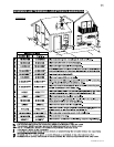
VENT LENGTHS
For optimum performance, it is recommended that horizontal runs
have a minimum 1/4” rise per foot when using Wolf Steel,
Simpson Dura-Vent, Selkirk Direct Temp, or American Metal
Amerivent rigid vent components and a minimum of 1” rise per
foot when using Wolf Steel flexible vent components.
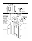
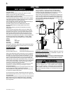
When venting, the horizontal run must be kept to a maximum of
20 feet. If a 20 foot horizontal run is required, the fireplace must
have a minimum vertical rise immediately off the fireplace of 57”.
When terminating vertically, the vertical rise is a minimum 3 feet
and a maximum 40 feet above the fireplace.
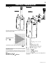
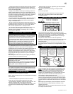
16”
MINIMUM
24” MAXIMUM
10”
MINIMUM
56”
PLUS RISE*
12” MINIMUM
30”
MINIMUM
MAXIMUM 10 FOOT VENT LENGTH
CAN BE USED WITH GD201 PERISCOPE KIT
* REFER TO “VENTING” SECTION
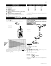
INSULATION
SLEEVE
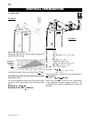
40 FEET
MAXIMUM
3 FEET
MINIMUM
* FIRST
2 FEET
REQUIRES
INSULATION
SLEEVE
FIGURES 3a-b
FIGURE 4
* The fi rst 2 feet of outer 7 “ diameter vent pipe from the appliance
must be wrapped in the 1” thick insulation sleeve (supplied).
Make sure the insulation is pulled down tight to the fi replace
when installed. There after, a 2” clearance all around the vent
pipe from combustible materials on all horizontal vent sections
is required.
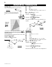
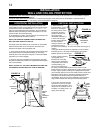
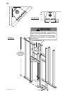
!
WARNING
HORIZONTAL VENT SECTIONS: A minimum clearance of 2” all around
the vent pipe on all horizontal runs to combustibles is required. Use
fi restop spacer W010-1799 (supplied).
VERTICAL VENT SECTIONS: A minimum of 1” all around the vent pipe
on all vertical runs to combustibles is required except for clearances in
fi replace enclosures. Use fi restop spacer W500-0096 (not supplied).