


Special offers from our partners!

Find Replacement BBQ Parts for 20,308 Models. Repair your BBQ today.
22
W415-0665 / B / 02.11.08
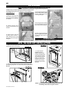
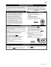
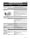
Your comes equipped with our “Night Light™”. The
light has been pre-wired and is controlled from the remote control.
If in the event the lamp or lens needs to be replaced, follow the
instructions below.
Unplug the wire harness / transformer from the FCM (Fan Control
Module) inside the fi replace.
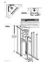
NIGHT LIGHT™ REPLACEMENT
SCREWS
LENSE
FRAME
FIREBOX TOP
Remove the four screws that
secure the lens frame.
This frame retains the glass
lens. The lamp can now be
accessed.
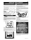
Note: Do not handle the lamp
(bulb) with bare fi ngers, protect
with a clean dry cloth.
The lamp will pull straight out
of the socket. Replace with
Wolf Steel parts only, as lamp
and lens are special “high
temperature” products.
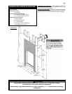
When re-installing, ensure integrity of gasket seal.
THE FIREBOX MUST BE SEALED.
Over tightening the screws could break the lens.
“Light Leakage” from the upper area may be observed. The
holes in the lamp housing are necessary for ventilation and
must not be covered.
FIGURE 54
FIGURE 56
GASKET
LENSE
FRAME
COLOURED SIDE UP
OPERATION
FIGURE 55
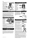
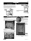
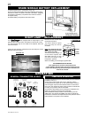
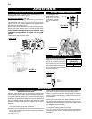
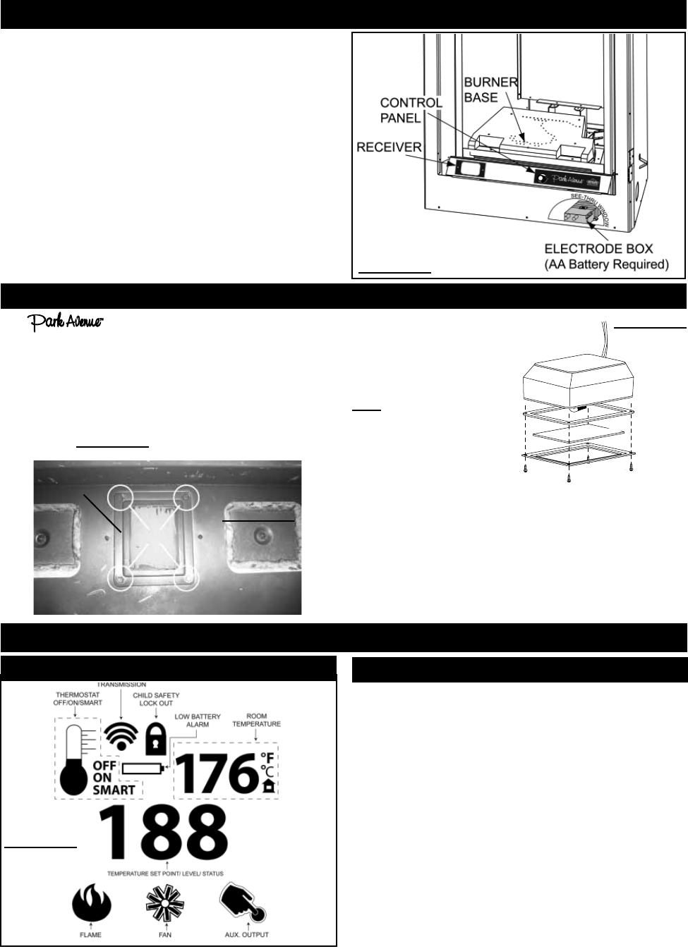
SPARK MODULE BATTERY REPLACEMENT
1. Remove optional front. (Instructions on Pg. 19)
2. Tilt the control panel forward and remove allowing access to the
electode box which is screwed to the base of the fi rebox. (Fig. 53)
3. Pull back on the battery compartment door latch and remove.
4. Replace battery.
5. Reinstall battery compartment and control doors.
FIGURE 53
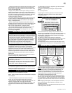
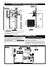
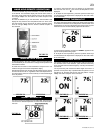
1. Install 4 AA batteries into the receiver battery bay as indicated on
the battery cover (+/-).
2. Place the 3 position slider switch in the “Remote” position.
3. Using the end of a paper clip, or other similar object, insert the
end of the paper clip into the hole marked “PRG” on the receiver
front cover. The receiver will “beep” three (3) times to indicate that
it is ready to synchronize with the transmitter.
4. Install the 3 AAA batteries in the transmitter as indicated in the
battery bay, located on the base of the transmitter.
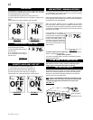
With the batteries already installed in the transmitter, push the
“ON” button. The receiver will “beep” four times to indicate the
transmitter’s command is accepted and set to the particular code of
that transmitter. The system is now initialized.
GENERAL TRANSMITTER LAYOUT
FIREPLACE OPERATION
FIGURE 57