


Special offers from our partners!

Find Replacement BBQ Parts for 20,308 Models. Repair your BBQ today.
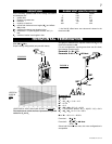
13
W415-0665 / B / 02.11.08
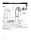
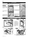
USING FLEXIBLE VENT COMPONENTS
ELBOW
SPACERS
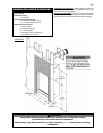
!
WARNING
Note: Direct vent
terminals shall
not be recessed
into a wall or
siding.
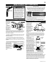
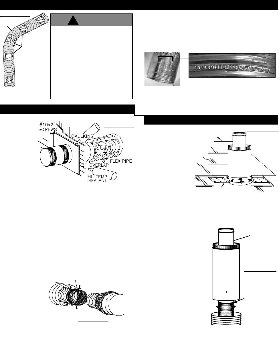
1. Stretch the
4" diameter
flexible vent pipe
to the required
length taking into
account the
additional length
needed for the finished wall surface. Slip the liner a minimum of
2" over the inner sleeve of the air terminal and secure with 3 #8
screws. Apply a heavy bead of the high temperature sealant
W573-0007 (not supplied).
2. Using the 7” diameter flexible vent pipe, slide over the outer
combustion air sleeve of the air terminal and secure with 3 #8
screws. Seal as before.
3. Insert the vent pipe through the firestop maintaining the
required clearance to combustibles. Secure to the exterior wall
and make weather tight by sealing with caulking W573-0002 (not
supplied).
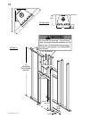
4. If more vent pipe needs to be used to reach the fireplace,
couple them together as illustrated in (Fig. 20). The vent system
must be supported
approximately every 3
feet for both vertical
and horizontal runs.
Use non-combusible
strapping to maintain
the minimum 1”
clearance to combus-
tibles.
HIGH TEMP
SEALANT
#8 X 1/2” SELF DRILLING
SCREWS & WASHERS
7” FLEX
PIPE
4” FLEX
PIPE
7” FLEX PIPE
4” COUPLER
7” COUPLER
CAULKING
SCREWS
#10x2"
PIPE
8" FLEX
2" OVERLAP
SEALANT
HI-TEMP
5"FLEX
PIPE
HIGH TEMP
SEALANT
#8 X 1/2” SELF DRILLING
SCREWS & WASHERS
7” FLEX
PIPE
4” FLEX
PIPE
7” FLEX PIPE
4” COUPLER
7” COUPLER
CAULKING
SCREWS
#10x2"
PIPE
8" FLEX
2" OVERLAP
SEALANT
HI-TEMP
5"FLEX
PIPE
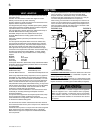
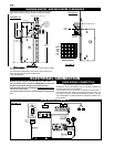
HORIZONTAL AIR TERMINAL INSTALLATION
VERTICAL AIR TERMINAL INSTALLATION
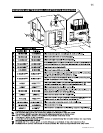
For safe and proper operation of the fireplace, follow the venting
instructions exactly.
All inner exhaust and outer intake vent pipe joists may be sealed
using either red RTV high temp silicone sealant or black high
temp Mill Pac with the exception of the fireplace exhaust flue
collar which must be sealed using Mill Pac (not supplied).
Six inches (6”) is the minimum bend radius allowed for the seven
inch (7”) diameter flexible vent pipe.
For optimum performance it is recommended that all horizontal
runs have a minimum 1” rise per foot using flexible venting.
“Wolf Steel Approved Venting” as identified
by the stamp only on the 7” outer vent pipe.
Use only approved flexible vent pipe kits marked:
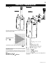
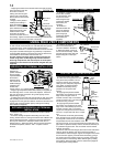
1. Move the fireplace into position.
2. Fasten the roof
support to the roof
using the screws
provided. The roof
support is optional. In
this case the venting is
to be adequately
supported using either
an alternate method
suitable to the authority
having jurisdiction or
the optional roof
support.
3. Stretch the inner flexible vent pipe to the required length.
Slip the liner a minimum of 2” over the inner vent pipe of the air
terminal connector and secure with 3 #8 screws. Seal using a
heavy bead of the high temperature sealant W573-0007 (not
supplied).
4. Repeat using the outer
flexible vent pipe.
5. Thread the air terminal
connector / pipe assembly
down through the roof. The air
terminal must be located
vertically and plumb. Attach
the air terminal connector to the
roof support, ensuring that the
top of the air terminal is 16”
above the highest point that it
penetrates the roof. If the attic
space is tight, we recom-
mend threading the Wolf
Steel vent pipe collar or
equivalent loosely onto the
air terminal assembly as it is
passed through the attic.
6. Remove nails from the
shingles, above and to the
sides of the chimney. Place the flashing over the air terminal
connector leaving a min. 3/4” of the air terminal connector
showing above the top of the flashing. Slide the flashing
underneath the sides and upper edge of the shingles. Ensure that
the air terminal connector is properly centred within the flashing,
giving a 3/4” margin all around. Fasten to the roof. Do not nail
through the lower portion of the flashing. Make weather-tight by
sealing with caulking. Where possible, cover the sides and top
edges of the flashing with roofing material.
ROOF SUPPORT
AIR
TERMINAL
CONNEC-
TOR
INNER FLEXIBLE
VENT PIPE
OUTER FLEXIBLE
VENT PIPE
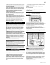
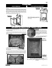
INNER
PIPE
HIGH
TEMPERATURE
SEALANT
DO NOT CLAMP THE
FLEXIBLE VENT PIPE
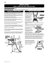
Do not allow the inside vent pipe to
bunch up on horizontal or vertical runs
and elbows. Keep it pulled tight. A 1
1/4” air gap between the liner and the
outer liner all around is required for
safe operation. A spacer is required at
the start, middle and end of each
elbow to ensure this gap is maintained.
Spacers are attached to the inner
flexible vent pipe at predetermined
intervals to maintain a 1 1/4" air gap to
the outer flexible vent pipe. These
spacers must not be removed.
FIGURE 21
FIGURE 22a
FIGURE 19
FIGURE 22b
FIGURE 20