


Special offers from our partners!

Find Replacement BBQ Parts for 20,308 Models. Repair your BBQ today.
21
W415-0665 / B / 02.11.08
SERVICING / REPLACEMENTS
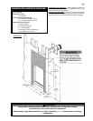
1a. Rectangular Front Removal
Pull on the top of the optional front away from the fi replace until the
male portion of the latch disengages. Tilt forward slightly and lift from
the 2 shoulder screws near the bottom.
1b. Heritage and Wrought Iron Front Removal
Turn the head of each turn button from a horizontal position to verti-
cal. Allow the front to tilt forward slightly and lift from the 2 shoulder
screws near the bottom front. Note: Fronts are heavy so when the
second turn button is turned the front will want to fall forward.
See Figure 51.
2. Control Panel Removal
Tilt control panel away from the door and lift from slots. See Figure
53.
3. Turn Power and Gas off to the unit.
4. Door Removal.
See door removal section.
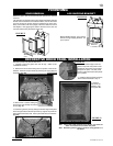
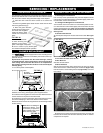
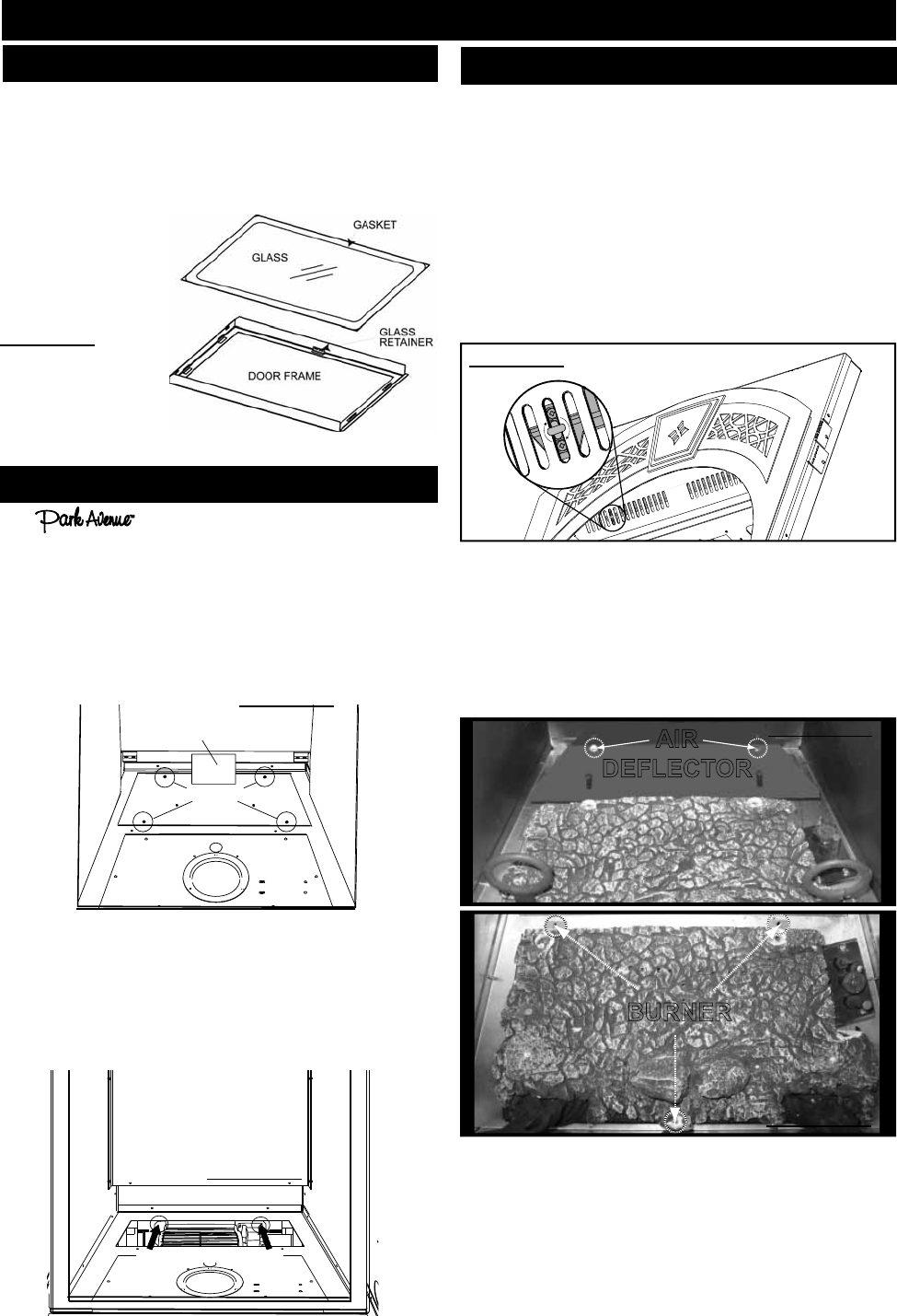
5. Burner Removal
Start by removing the logs being careful since the logs may still be
warm. Remove the 2 screws holding the air defl ector (Figure 52a)
then remove the 3 screw holding the burner (Figure 52b). Lift burner
from fi rebox.
6. Remove the 5 screws securing the burner base. Once the gas
has been disconnected, the valve train assembly will lift out. Service
components as required.
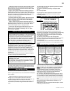
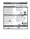
BURNER AND VALVE REPLACEMENT
FIGURE 51
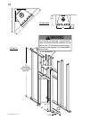
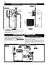
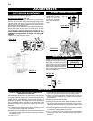
REMOVE 4 SCREWS
BLOWER
MOUNTING PLATE
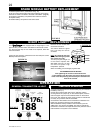
BLOWER REPLACEMENT
Your comes equipped with a heat circulating blower.
The blower is pre-wired and is controlled by the remote control sup-
plied with the unit.
Drywall dust will penetrate into the blower bearings, causing
irreparable damage. Care must be taken to prevent drywall dust
from coming into contact with the blower or its compartment.
Any damage resulting from this condition is not covered by the
warranty policy.
1. Turn off the power to the fi replace.
2. Turn off the gas valve.
3. Remove the glass door, logs, rear log supports, brick panels, air
defl ector, burner assy, panel support, panel support bracket.
4. The blower mounting plate can now be removed. Remove the four
screws that secure the plate to the fi rebox base.
5. The blower is secured to the fi rebox. Disconnect the wire connec-
tors before attempting to remove the blower from the fi rebox.
6. Remove the two screws securing the blower and lift through blower
access opening.
FIGURE 49
REMOVE 2 SCREWS
Note: When re-installing the
replacement blower, it will
be necessary to replace the
gasket (W290-0104) on the
blower mounting plate.
FIGURE 50
AIR
DEFLECTOR
BURNER
FIGURE 52a
FIGURE 52b
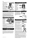
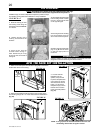
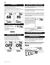
1. Place the door frame face down careful not to scratch the
paint.
2. Center the gasketed glass inside the door frame with the thick
side of the gasket facing up.
3. Bend the glass retainers
located along the edge of the
door frame over the gasket
holding the glass in place.
Careful not to break the
glass.
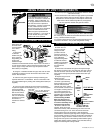
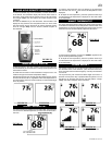
GLASS/DOOR REPLACEMENT
FIGURE 48
NOTE: Care must be tak-
en when removing and
disposing of any broken
glass or damaged components.
Be sure to vacuum up any broken glass
from inside the fi replace before operation.
The glass door is secured at the top front edge of the fi replace. Pull the
latch forward then lift hook out from slot in the door. Tilt door forward
then lift out from retainer along the bottom edge of the fi replace.