


Special offers from our partners!

Find Replacement BBQ Parts for 20,308 Models. Repair your BBQ today.
18
W415-0665 / B / 02.11.08
2”
2”
72”
26”
8”
56”
MINIMUM
PLUS RISE*
COMBUSTIBLE
NON-COMBUSTIBLE
BRICK
1”
COMBUSTIBLE
NON-
COMBUSTIBLE
0” IF NON-
COMBUSTIBLE
FINISHING IS
USED SUCH AS
BRICK AND
STONE
12 1/4”
INSULATION
SLEEVE
2”
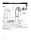
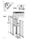
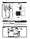
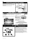
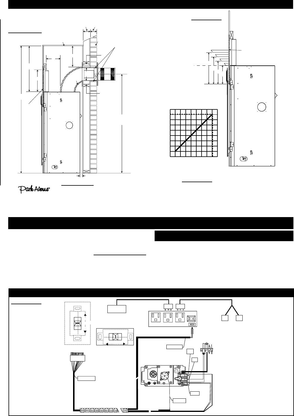
IMPORTANT:
The requires a minimum inside enclosure height
of 72”.
For temperature requirements, the enclosure space around and
above the fi replace must be left unobstructed.
* See venting section
0
34 7
8
9
11
13
12 56
7
10
12
H
E
I
G
H
T
M
A
N
T
E
L
MANTEL DEPTH
14
8
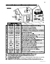
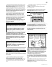
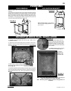
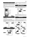
FIGURES 33
MINIMUM MANTEL AND ENCLOSURE CLEARANCES
Combustible mantel clearance can vary according to the mantel
depth. Use the graph to help evaluate the clearance needed.
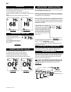
FIGURE 34
8” MANTEL
2”
4”
6”
14”
12”
10”
8”
TOP OF
FIREPLACE
OPENING
TOP OF
FIREPLACE
NON-COMBUSTIBLE
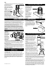
Do NOT use the fi replace if any part has been under water.
Call a qualifi ed service technician IMMEDIATELY to have the
fi replace inspected for damage to the electrical circuit.
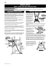
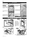
If access to the control area is necessary BEFORE INSTALLATION,
remove the access panel.
The access panel must be re-installed before operating the
unit.
It is necessary to hard wire this fi replace.
Permanently framing the fi replace with an enclosure, requires the
fi replace junction box to be hardwired.
This fireplace must be electrically connected and grounded in
accordance with local codes. In the absence of local codes, use
the current CSA C22.1 CANADIAN ELECTRICAL CODE in Canada
or the ANSI/NFPA 70-1996 NATIONAL ELECTRICAL CODE in the
United States.
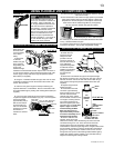
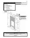
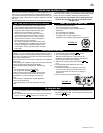
ELECTRICAL CONNECTION
HARD WIRING CONNECTION
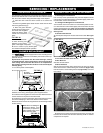
ELECTRICAL SCHEMATIC
FIGURE 36
FIGURE 35
RECEIVER
Receiver
12 Pin
Connector
110V OUT
Receiver Hearth Mount
OFF
ON
REMOTE
TPTH
TP
TH
FCM-COM
FAN AUX OUT
Red
Black
MOTOR
Green
White
Fan Control Module (FCM)
OUT
Modulating 820
Night Lights
ON
OFF
REMOTE
Receiver Wall Mount
BLOWER