


Special offers from our partners!

Find Replacement BBQ Parts for 20,308 Models. Repair your BBQ today.

15
W415-0665 / B / 02.11.08
MOBILE HOME INSTALLATION
This appliance is certified to be installed as an OEM (Original
Equipment Manufacturer) installation in a manufactured home
or mobile home and must be installed in accordance with the
manufacturer’s instructions and the Manufactured Home
Construction and Safety Standard, Title 24 CFR, Part 3280, in
the United States or the Mobile Home Standard, CAN/CSA
Z240 MH Series, in Canada. This appliance is only for use
with the type(s) of gas indicated on the rating plate. A
conversion kit is supplied with the mobile home appliance.
This Mobile/Manufactured Home Listed appliance comes factory
equipped with a means to secure the unit. The fireplace is
equipped with two 1/4” diameter holes located in the front left and
right corners of the base. For mobile home installations, the
fireplace must be fastened in place. Use #10 hex head screws,
inserted through the holes in the base to secure. Always turn off
the pilot and the fuel supply at the source, prior to moving the
mobile home.
A
fter moving the mobile home and prior to lighting the fireplace,
ensure that the logs are positioned correctly.
This appliance is certified to be installed in an aftermarket
permanently located, manufactured (mobile) home, where not
prohibited by local codes.
This fireplace is only for use with the type of gas indicated on
the rating plate. This fireplace is not convertible for use with
other gases, unless a certified kit is used.
Conversion Kits
The mobile home appliance is field convertible between Natural
Gas (NG) and Propane (LP).To convert from one gas to another
consult your Napoleon dealer/distributor.
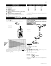
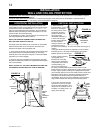
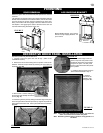
7. Aligning the seams o
f
the terminal and air terminal connector,
place the terminal over the air terminal connector making sure
the liner goes into the hole in the terminal. Secure with the three
screws provided. Figure 22c
8. Apply a heavy bead of weather-proof caulking 2” above the
flashing. NOTE: Maintain a minimum 2” space between the air
inlet base and the storm collar. Install the storm collar around the
air terminal connector and slide down to the caulking. Tighten to
ensure that a weather-tight seal between the air terminal
connector and collar is achieved.
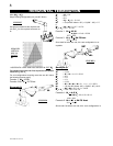
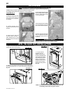
9. Continue adding rigid venting sections, sealing and securing
as above. Attach a 4" collapsed telescopic sleeve to the last
section of rigid piping. Secure with screws and seal. Repeat
using a 7" telescopic sleeve.
10. Run a bead of high temperature sealant W573-0007 (not
supplied) around the outside of the 4" collar on the fireplace. Pull
the telescopic sleeve a minimum of 2" onto the collar. Secure
with 3 screws. Repeat with the 7" telescopic sleeve.
11. In the attic, slide the vent pipe collar down to cover up the
open end of the shield and tighten. This will prevent any
materials, such as insulation, from filling up the 1" air space
around the pipe. Figure 27
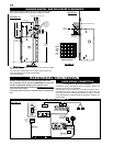
Proceed once the vent installation is complete.
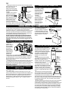
NOTE: All gas connections must be contained within the fireplace
when complete.
1. Move the fireplace into position and secure to the floor
through the 1/4" holes located at either side of the base.
2. The fireplace is designed to accept 3/8" gas supply line. The
fireplace is equipped with a 3/8" manual shut-off valve.
3. Connect the gas supply in accordance to local codes. In the
absence thereof, install according to the National Installation
Code.
GAS INSTALLATION
4
. When
f
lexing any gas line, support the gas valve so that the
lines are not bent or kinked.
5. Check for gas leaks by brushing on a soap and water
solution.
Do not use open flame.
Purge all gas lines with the glass door of the stove removed.
Assure that a continuous gas flow is at the burner before
re-installing the door.
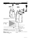
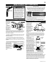
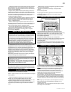
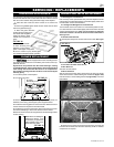
Vertical terminations may display a very active flame. If this
appearance is not desirable, the vent exit must be restricted using
restrictor plate, W500-0205. This reduces the velocity of the
exhaust gases, slowing down the flame pattern and creating a
more traditional appearance.
The plate has a series of holes to allow for adjustment.
Remove the two screws on either side of the exhaust collar inside
the firebox. Install the plate in the desired set of holes, then
replace the screws.
It is recommend to secure in the third set of holes which causes
the greatest amount of restriction for vent length between 15 and
30 feet.
RESTRICTING VERTICAL VENTS
TOP OF FIREBOX
RESTRICTOR PLATE
FLUE COLLAR
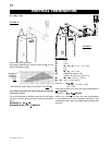
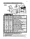
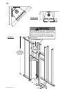
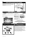
MINIMUM FRAMING CLEARANCES
WARNING
THE STANDOFFS HAVE
BEEN SHIPPED FLAT.
BEFORE FRAMING
ENSURE THE STANDOFFS
ARE BENT UP AND
SCREWED INTO PLACE.
ATTENTION ATENCIÓN
LAS TRABAS PERMANECEN
PLANAS DURANTE EL ENVÍO.
ANTES DE LA INSTALACIÓN,
VERIFIQUE QUE LAS TRABAS
SE PLIEGUEN HACIA ARRIBA
Y SE ATORNILLEN
CORRECTAMENTE.
LES ESPACEURS SONT
EMBALLÉS À PLAT. AVANT DE
CONSTRUIRE L'OSSATURE,
ASSUREZ-VOUS QUE LES
ESPACEURS SONT PLIÉS
ET FIXÉS EN PLACE À
L'AIDE DE VIS.
It is best to frame your fireplace after it is positioned and the vent
system is installed. Use 2x4’s and frame to local building codes.
NOTE: In order to avoid the possibility of exposed insulation or
vapour barrier coming in contact with the fireplace body, it is
recommended that the walls of the fireplace enclosure be
“finished” (ie: drywall/sheetrock), as you would finish any other
outside wall of a home. This will ensure that clearance to
combustibles is maintained within the cavity.
For convenience, the stand-offs have been shipped flat. Before
framing, ensure the stand-offs are opened and screwed in place.
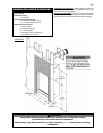
It is not necessary to install a hearth extension, but the fireplace
should be raised to be flush with either the hearth or the finished
floor.
When roughing in the fireplace, raise the fireplace to accommo-
date for the thickness of the finished floor materials, i.e. tile,
carpeting, hard wood.
Objects placed in front of the fireplace should be kept a minimum
of 48” away from the front face.
FIGURE 29
FIGURE 28