


Special offers from our partners!

Find Replacement BBQ Parts for 20,308 Models. Repair your BBQ today.
26
W415-0665 / B / 02.11.08
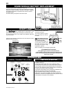
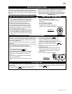
FIGURE 76
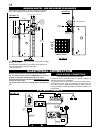
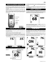
Adjust the pilot screw to provide properly sized fl ame. Turn in a
clockwise direction to reduce the gas fl ow.
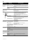
FIGURE 77
PILOT BURNER ADJUSTMENT
TURN OFF THE GAS AND ELECTRICAL POWER BEFORE
SERVICING THE FIREPLACE.
CAUTION: Label all wires prior to disconnection when servicing
controls. Wiring errors can cause improper and dangerous operation.
Verify proper operation after servicing. This fi replace and its venting
system should be inspected before use and at least annually by a
qualifi ed service person. The fi replace area must be kept clear and
free of combustible materials, gasoline or other fl ammable vapors
and liquids. The fl ow of combustion and ventilation air must not be
obstructed.
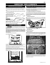
1. In order to properly clean the burner and pilot assembly, remove
the log and burner to expose both assemblies.
2. Keep the control compartment, log, burner, air shutter opening and
the area surrounding the logs clean by vacuuming or brushing,
at least once a year.
3. Check to see that all burner ports are burning. Clean out any of the
ports which may not be burning or are not burning properly.
4. Check to see that the pilot fl ame is large enough to engulf the
thermocouple and thermopile and reaches toward the burner
with the third jet.
5. Replace the cleaned log and burner.
6. Check to see that the main burner ignites completely on all open-
ings when the gas knob for the burner is turned on. A 5 to 10 second
total light-up period is satisfactory. If ignition takes longer, consult
your Napoleon
®
dealer / distributor.
7. Check that the gasketing on the sides, top and bottom of the door
is not broken or missing. Replace if necessary.
8. If for any reason the vent air intake system is disassembled,
reinstall and re-seal per the instructions provided for the initial
installation.
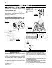
3/8” - 1/2”
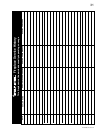
It is important to peri-
odically perform a visual
check of the pilot and
burner fl ames. Compare
them to the illustration
below.
FLAME CHARACTERISTICS
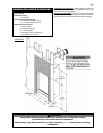
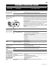
Check Pressure Readings: (Fig. 76)
Inlet pressure can be checked by turning screw (A) counter-clock-
wise 2 or 3 turns and then placing pressure gauge tubing over the
test point. Gauge should read 7” (minimum 4.5”) water column for
natural gas or 13” (11” minimum) water column for propane. Check
that main burner is operating on “HI”.
Outlet pressure can be checked the same as above using screw (B).
Gauge should read 3.5” water column for natural gas or 10” water
column for propane. Check that main burner is operating on “HI”.
AFTER TAKING PRESSURE READINGS, BE SURE TO TURN
SCREWS CLOCKWISE FIRMLY TO RESEAL. DO NOT OVER-
TORQUE.
Leak test with a soap and water solution.
PILOT
SCREW
A
B
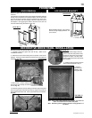
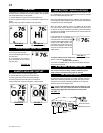
FIGURE 78
Closing the air shutter will cause a more
yellow fl ame, but can lead to carboning.
Opening the air shutter will cause a
more blue fl ame, but can cause fl ame
lifting from the burner ports. The fl ame
may not appear yellow immediately; al-
low 15 to 30 minutes for the fi nal fl ame
color to be established.
AIR
SHUTTER
OPENING
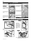
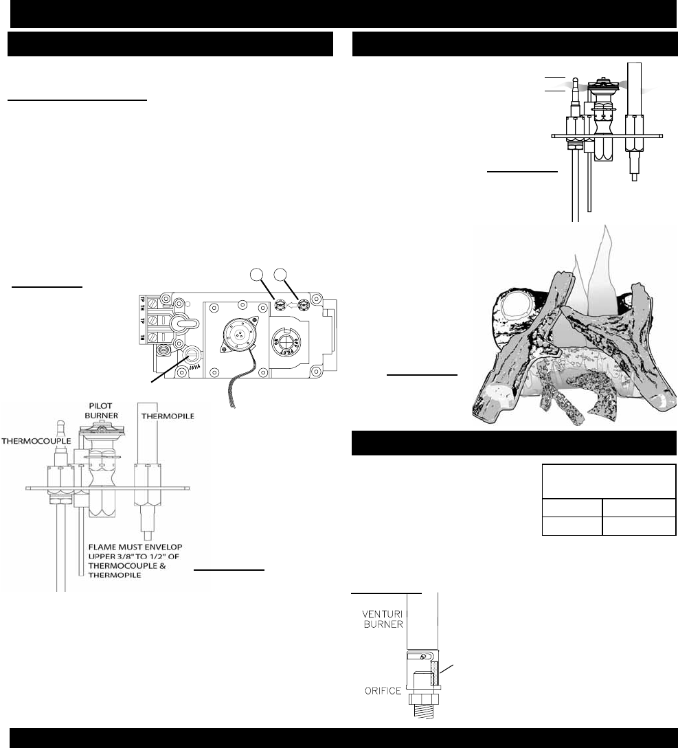
FIGURE 80
VENTURI ADJUSTMENT
AIR SHUTTER
OPENINGS
LP 1/2”
NG 1/16”
FIGURE 79
ADJUSTMENTS
MAINTENANCE