


Special offers from our partners!

Find Replacement BBQ Parts for 20,308 Models. Repair your BBQ today.
10
W415-0665 / B / 02.11.08
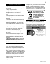
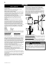
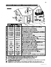
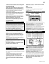
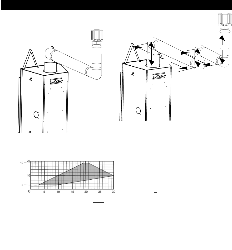
MAXIMUM
VERTICAL
RISE IN
FEET
V
T
HORIZONTAL VENT RUN PLUS OFFSET IN FEET
H
T
The shaded area within the lines represents acceptable
values for H
T
and V
T
.
Simple venting confi gurations
See graph to determine the required vertical rise V
T
for the
required horizontal run H
T
.
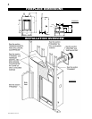
FIGURE 13
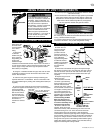
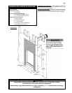
Example 5:
V
1
= 2 ft
V
2
= 1 ft
V
3
= 1.5 ft
V
T
=
V
1
+
V
2
+
V
3
=
2 + 1 + 1.5 = 4.5 ft
H
1
= 6 ft
H
2
= 2 ft
H
R
= H
1
+ H
2
= 6 + 2 = 8 ft
H
O
= .03(four 90° elbows - 90°)
= .03(90 + 90 + 90 + 90 - 90) = 8.1 ft
H
T
= H
R
+ H
O
= 8 + 8.1 = 16.1 ft
H
T
+ V
T
= 16.1 + 4.5 = 20.6 ft
Formula 1: H
T
< 3V
T
3V
T
=
3 x
4.5 = 13.5 ft
16.1 > 13.5
Since this formula is not met, this vent confi guration is
unacceptable.
Formula 2: H
T
+ V
T
< 40 feet
20.6 < 40
Since only formula 2 is met, this vent confi guration
is unacceptable and a new fi replace location or vent
confi guration will need to be established to satisfy both
formulas.
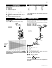
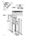
FIGURE 12
H
1
H
2
V
3
V
1
90°
90°
90°
V
2
90°
when (H
T
) > (V
T
)
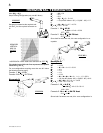
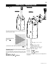
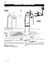
VERTICAL TERMINATION
For vent confi gurations requiring more than two 90° elbow
(top exit) or one 90° elbow (rear exit), the following formulas
apply:
Formula 1: H
T
< 3V
T
Formula 2: H
T
+ V
T
< 40 feet