


Special offers from our partners!

Find Replacement BBQ Parts for 20,308 Models. Repair your BBQ today.
9
www.desatech.com
116035-01B
VENTING INSTALLATION
INSTRUCTIONS
Continued
IMPORTANT:
Horizontal square terminations require only inner
portion of wall firestop. Horizontal installation using round termina-
tion require exterior portion of wall firestop (see Figure 18, page 11).
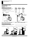
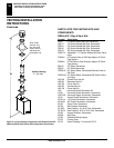
1. Set the fireplace in its desired location and determine the route
your horizontal venting will take. Do not secure the fireplace
until all venting has been installed. Some installations require
sliding the fireplace in and out of position to make final venting
connections. Figures 19 through 25 on pages11 through 13 show
different configurations for venting with horizontal termina-
tion that will help you decide which application best suits your
installation. Check to see if wall studs or roof rafters are in the
path of your desired venting route. If they are, you may want
to adjust the location of the fireplace.
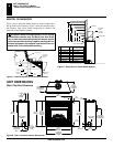
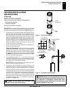
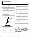
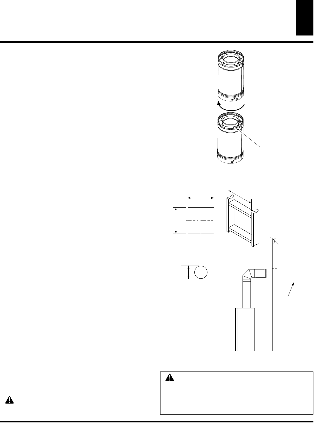
2. Direct vent pipe sections and components are designed with
special twist-lock connections.
Twist-Lock Procedure: The female ends of the pipes have
locking lugs (indentations). These lugs will slide straight into
matching slots on the male ends of adjacent pipes. Push pipe
sections together and twist one section clockwise approximately
one-quarter turn until the sections are fully locked (see Figure
11).
Note:
Horizontal runs of vent must be supported every three
feet. Use wall strap for this purpose.
3. Any straight pipe section, a 45°, or a 90° elbow can be used
when first connecting the venting system to the fireplace. Elbows
are designed to twist lock into any of four 90° positions to direct
the venting system to the desired location.
IMPORTANT:
Do not attempt to alter the configuration of the
elbows by cutting, twisting, bending, etc.
4. Assemble the desired combination of pipe and elbows to the
fireplace flue collar. If there are long portions of venting run,
pipe sections may be pre-assembled and installed for convenience.
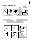
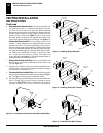
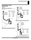
5. Carefully determine the location where the vent pipe assembly
will penetrate the outside wall. The center of the hole should line
up with the center-line of the horizontal vent pipe. Mark the wall
for a 10 ¾” x10 ¾” square hole. Cut and frame the square hole
in the exterior wall where the vent will be terminated. If the wall
being penetrated is constructed of noncombustible material, such
as masonry block of concrete , a 8 ½” hole with zero clearance is
acceptable (see Figure 12).
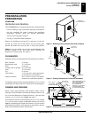
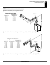
INSTALLATION PLANNING
There are two basic types of direct-vent installations:
• Horizontal Termination
• Vertical Termination
Horizontal Termination Installation
Female
Locking Lugs
Male
Slots
Figure 11 - Vent Pipe Connection
(Framing
Detail)
10
3
/4"
(273mm)
10
3
/4" Inside Framing
(273mm)
10
3
/4"
(273mm)
8
1
/2"
(216mm)
Vent Opening
Combustible
Wall
Vent Opening
Noncombustible
Wall
Center
of
Hole
Figure 12 - Vent Opening Requirements
VENTING INSTALLATION INSTRUCTIONS
Installation Planning (Cont.)
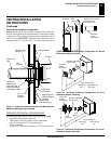
WARNING:
Do not recess vent termination into
any wall. This will cause a fire hazard.
WARNING:
Never run vent downward as this may
cause excessive temperatures which could cause a
fire. Operation of improperly installed and main-
tained venting system could result in serious injury,
property damage or loss of life.