


Special offers from our partners!

Find Replacement BBQ Parts for 20,308 Models. Repair your BBQ today.
15
www.desatech.com
116035-01B
VENTING INSTALLATION INSTRUCTIONS
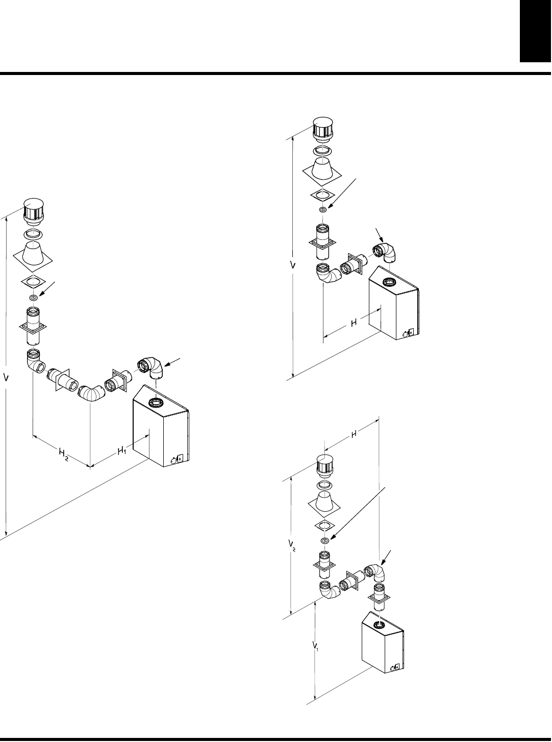
Installation for Vertical Termination (Cont.)
VENTING INSTALLATION
INSTRUCTIONS
Continued
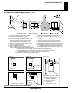
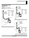
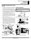
Vertical Termination Configurations
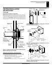
Figures 28 through 31 show four different configurations for verti-
cal termination.
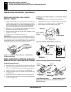
Venting with Three 90° Elbows
Vertical (V)
Horizontal (H
2
)
Horizontal (H
1
) +
8' min. 5' max.
10' min.
8' max.
12' min.
11' max.
14' min.
14' max.
16' min.
17' max.
90° Elbow
Note:
Install
restrictor ring
into inner pipe
section prior to
attaching vent
termination cap.
18' min.
20' max.
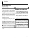
40' max.
20' max.
90° Elbow
Note:
Install
restrictor ring
into inner pipe
section prior to
attaching vent
termination cap.
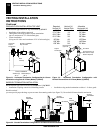
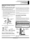
Venting with Two 90° Elbows
Vertical (V)
Horizontal H
8' min.
6' max.
9' min. 8' max.
10' min. 10' max.
12' min. 14' max.
14' min. 18' max.
40' max. 20' max.
90° Elbow
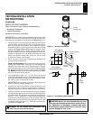
Note: Vertical (V
1
) + Vertical (V
2
) = 40' max.
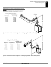
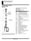
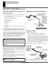
Venting with Two 90° Elbows
Vertical (V
1
)
Horizontal (H)
8' min. 9' max.
9' min.
11' max.
10' min.
13' max.
12' min.
17' max.
14' min.
20' max.
Note:
Install
restrictor ring
into inner pipe
section prior to
attaching vent
termination cap.
Max. Horizontal Above 14' Vertical = 20'
Figure 28 - Vertical Venting Configuration using Three 90° Elbows
(Model (V)CD36T with Vertical Round High Wind Termination)
Figure 29 - Vertical Venting Configuration Using Two 90° Elbows
(Model (V)CD36T with Vertical Round High Wind Termination)
Figure 30 - Vertical Venting Configuration Using Two 90° Elbows
(Model (V)CD36T with Vertical Round High Wind Termination)