


Special offers from our partners!

Find Replacement BBQ Parts for 20,308 Models. Repair your BBQ today.
17
www.desatech.com
116035-01B
ELECTRICAL SUPPLY CONNECTION
OPTIONAL BLOWER INSTALLATION
ELECTRICAL SUPPLY CONNECTION
CAUTION:
Disconnect the electrical power to the
supply circuit before attempting to connect or service
this appliance.
WARNING:
This appliance, when installed must be
electrically grounded in accordance with local code or
in the absence of local code, with the current National
Electric Code, ANSI/NFPA 70, or the Canadian Electric
Code, CSA C22.1.
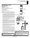
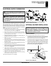
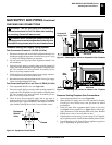
A pre-wired junction box receptacle with strain relief is provided on the
right side of the cabinet for hard wiring the unit to a 15 Amp, 120VAC,
60Hz grounded branch circuit. If the installation demands that the
electrical supply be connected from the left side, the entire receptacle
box can be relocated to the left side by following these instructions:
Note:
If you do not need to relocate the junction box, to connect the
electric supply follow steps 8 through 11 only:
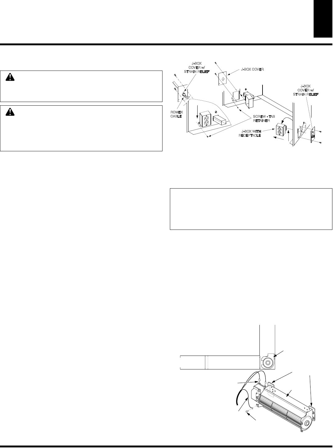
1. Remove the 2 screws and outer cover with strain relief bushing
on the right side of the cabinet (see Figure 32).
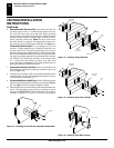
2. Remove inner retaining screw on the junction box mounting tab.
3. Slide the junction box up until the screw mounting tab is lined
up to the notch in the outer cabinet.
4. Swing the junction box out and slip the retaining flange out
through the slot in the outer cabinet.
5. Remove the two screws and outer cover on the left side
of the outer cabinet.
6. Reinsert the junction box retaining flange through the slot now
on the left side and swing the screw mounting tab back through
the notch as before.
7. Slide the junction box down till the mounting tab holes line up
and replace the inner retaining screw.
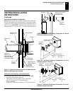
8. With the junction box cover removed, pull the end of 3-wire
Romex supply line through the universal strain relief bushing
on the cover. (see Figure 32).
9. Strip back the outer Romex to about 4” and connect the black,
white and green wires accordingly using 3 wire nut connectors.
10. Tuck the tailing wires into the junction box and replace the
junction box cover using the 2 remaining screws.
11. Tighten down the strain adjustment on the universal bushing
until the Romex sheathing is secured.
The electrical connection is now complete.
J-BOX WITH
RECEPTACLE
J-BOX
COVER w/
STRAIN RELIEF
J-BOX COVER
SCREW - TAB
RETAINER
J-BOX
COVER w/
STRAIN RELIEF
ROMEX
CABLE
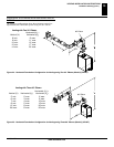
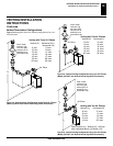
Figure 32 -
Relocating Junction Box Receptacle and
Electrical Supply Connection
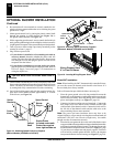
OPTIONAL BLOWER INSTALLATION
Model BK Installation
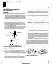
Follow all instructions provided in the blower accessory kit:
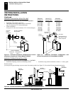
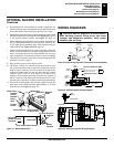
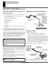
1. Attach the power cord to the blower motor by firmly pushing the
two female terminals at the end of the power cord onto the two
spade terminals on the blower motor (see Figure 33).
2. Attach green ground wire from power cord to blower housing
using screw provided (see Figure 33). Tighten screws securely
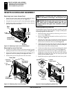
3. Place the blower against the lower rear wall of the firebox outer
wrapper with the exhaust port directed upward. The blower
will fit inside the back opening and be held in position against
the back wall by the magnets (see Figure 33).
Magnetic Strips
Exhaust
Port
Screw
Green
Ground
Wire
Spade Terminals
Side View
Lower
Firebox
Cavity
Blower
Location
NOTICE: If installing the blower in an existing fireplace
with gas connections, shut off the gas supply to the
fireplace before attempting to service this appliance.
If it is necessary to disconnect the gas supply, contact
a qualified service person to do this.
Figure 33 -
Blower Model BK
Models BK and BKT