


Special offers from our partners!

Find Replacement BBQ Parts for 20,308 Models. Repair your BBQ today.
29
www.desatech.com
116035-01B
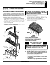
OPERATING FIREPLACE
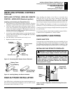
Operating Optional GWMT1 Wall Mounted Thermostat
Operating Optional Blower Accessory
INSPECTING BURNERS
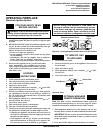
Pilot Assembly
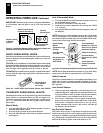
Burner Flame Pattern
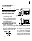
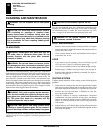
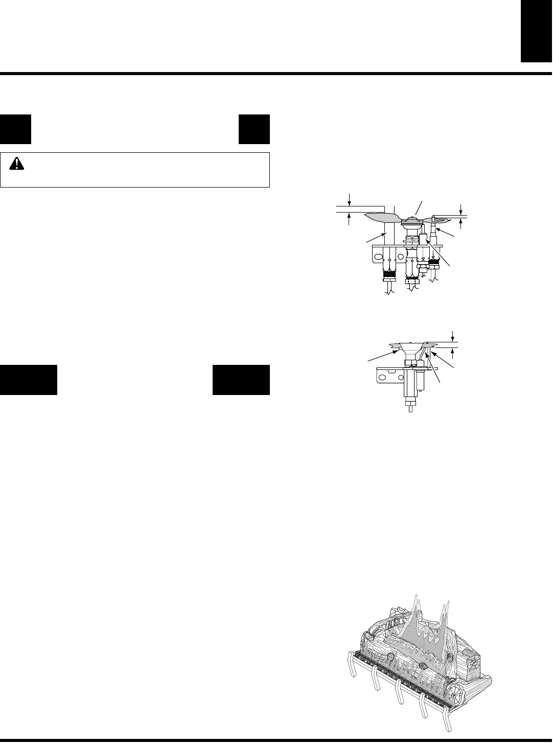
Figure 66 -
Typical Flame Pattern
OPERATING FIREPLACE
Continued
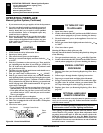
OPERATING OPTIONAL GWMT1
WALL MOUNTED THERMOSTAT
WARNING: Do not connect the thermostat to a
120 VAC power source. Damage or injury may occur.
Light the fireplace as instructed in Lighting Instructions on
page 26. Set wall thermostat to desired temperature.
This thermostat has been electronically calibrated at the factory
and requires no adjustment or leveling.
Upon installation, the thermostat must be allowed to stabilize at
room temperature for a minimum of 30 minutes for proper
operation.
To turn the fireplace off, adjust thermostat to the lowest setting
and turn the gas control knob back to PILOT. The pilot will
remain lit.
IMPORTANT:
To turn the pilot off, turn the gas control knob
on the heater to the OFF position.
OPERATING OPTIONAL
BLOWER ACCESSORY
Blower control is located on the ignitor bracket to the right of
the gas control behind the lower louver panel.
The BK manual blower and the BKT thermostatically con-
trolled blower have a control knob to turn on the blower and
adjust the fan speed. Rotating the knob approximately 1/4 turn
will switch the blower ON in the high position. Turning the
knob further will reduce the blower speed to the lowest position.
To turn the blower off, rotate the knob back until it clicks off.
Note for BKT Only:
If you are using a BKT blower, the blower
will not turn on until the fireplace has been burning for several
minutes and is sufficeintly heating. The blower control works
independent of the gas control, wall mounted switch or remote
control s. For the BKT blower to operate automatically the speed
control knob must be left in the on position prior to turning
on the fireplace either manually or remotely.
The blower helps distribute heated air from the fireplace.
Periodically check the louver of the fireplace and remove any
dust, dirt or other obstructions that will hinder the flow of air.
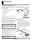
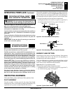
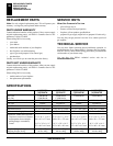
INSPECTING BURNERS
The position and pattern of the pilot flames in relation to the sens-
ing devices should be as shown in Figures 64 and 65 respectively.
The pilot flame may need adjustment in order for the thermocou-
ple, thermopile and/or the ignition system to sense the pilot flame.
If your pilot assembly does not meet these requirements:
• turn fireplace off (see To Turn Off Gas to Appliance, page 26 or 27)
• see sections under Troubleshooting, pages 31 through 35
1/8"
Pilot
Burner
3/8" to 1/2"
Thermo-
pile
Thermo-
couple
Piezo
Ignitor
BURNER FLAME PATTERN
Burner flames will be steady; not lifting or floating. Flame patterns
will be different from unit to unit and will vary depending on
installation type and weather conditions.
If the vent configuration is installed incorrectly, the flames will lift
or “ghost”. This can be dangerous. Inspect the flames after installa-
tion to ensure proper installation and performance.
Figure 66 shows a typical flame pattern.
If burner flame pattern differs from that described:
• turn fireplace off (see To Turn Off Gas to Appliance, page 26 or 27)
• see Troubleshooting, pages 31 through 35
Figure 64 -
Pilot Assembly (Millivolt System)
Check pilot flame pattern and burner flame patterns often.
PILOT ASSEMBLY
The pilot assembly is factory preset for the proper flame height
Alterations may have occurred during shipping and handling. Call
a qualified service person to readjust the pilot if necessary.
Pilot Burner
Ignitor
Sensor Rod
1/4"
Figure 65 -
Pilot Assembly (Electronic Ignition System)