


Special offers from our partners!

Find Replacement BBQ Parts for 20,308 Models. Repair your BBQ today.
19
www.desatech.com
116035-01B
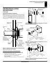
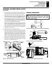
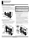
Thermodisc
Air Flow Direction
Route BKT
Blower
Through
This
Area
Magnets
Blower
Location
Side View Firebox Bottom
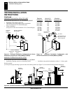
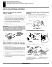
Black
Wire
Phillips
Screw
Blue Wire
Ring
Terminal
on Green Wire
White Wire
Thermal
Switch
Thermal
Switch
Bracket
Power Cord
Air Flow
Direction
Magnetic
Strips
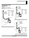
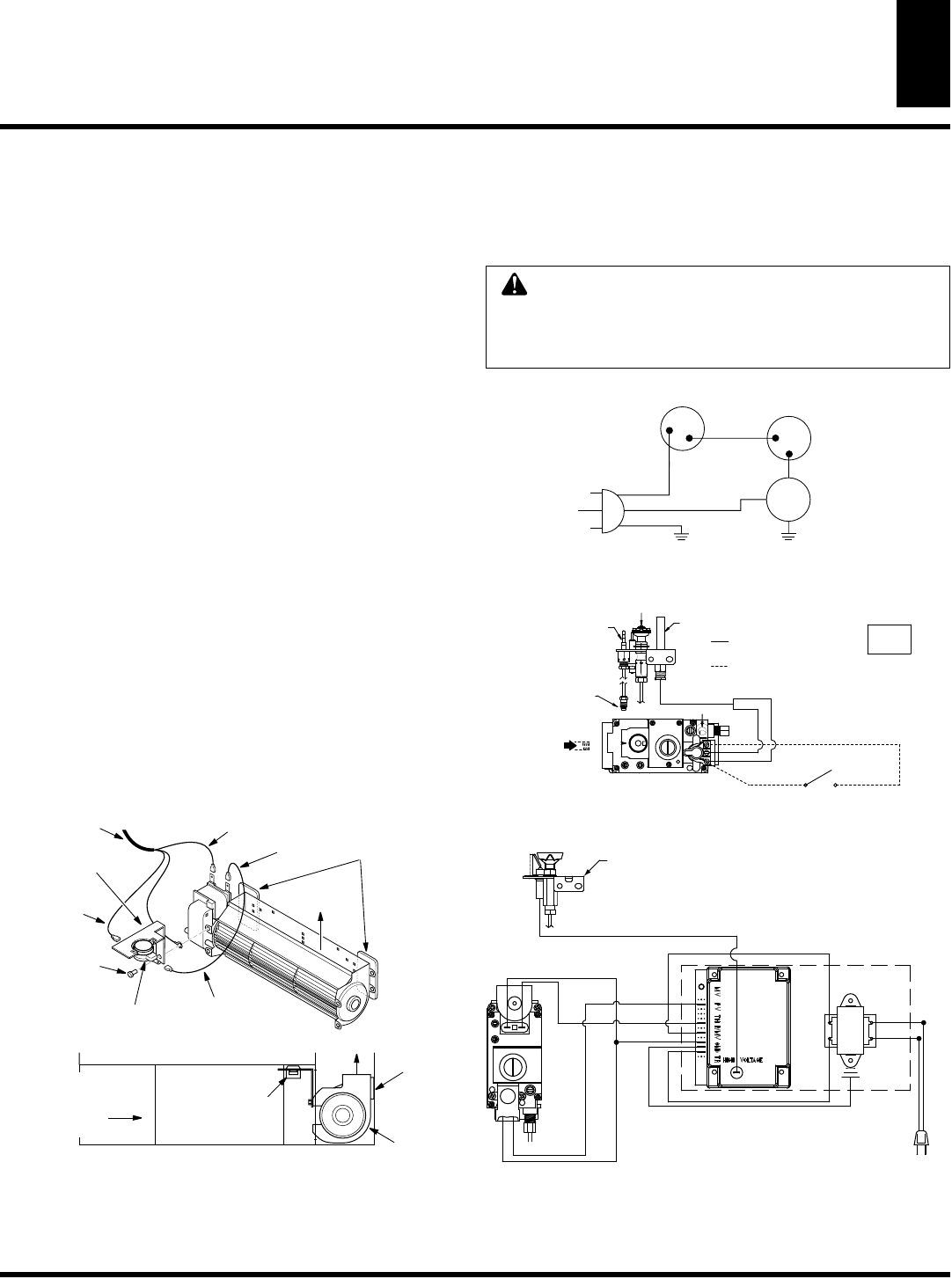
Figure 37 -
Blower Model BKT
OPTIONAL BLOWER INSTALLATION
Continued
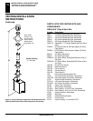
OPTIONAL BLOWER INSTALLATION (Cont.)
Models BK and BKT)
WiIRING DIAGRAMS
4. Be certain that all wire terminals are securely attached to ter-
minals on blower motor and thermal switch, and that the screw
for the thermodisc bracket and green ground wire is tight.
5. Mount the speed control box by placing the plastic control shaft
through the opening in switch bracket (see Figure 34, page 18)
or the ignition module bracket (see Figure 35, page 18)
6. While supporting speed control, secure control shaft with lock
nut by pushing and turning lock nut with pliers clockwise un-
til it is tight against mounting plate. Place control knob pro-
vided on shaft (see Figure 34 or 35, page 18).
7.
Check to make sure that the power cord is completely clear of the
blower wheel and that there are no other foreign objects in blower
wheel. Also double check all wire leads and make sure wire rout-
ing is not pinched or in a precarious position. Correct accordingly.
8. Turn on power to duplex outlet if previously turned off per the
warning in column 1, page 17.
9. Plug in blower power cord to duplex outlet.
10. The blower will only run when the speed control knob is in the
ON position and the thermal switch senses temperature after the
fireplace begins to heat up. The blower speed can be adjusted by
rotating the control knob. To turn off, turn knob fully counter-
clockwise until it clicks off. If the blower is ON and has been
running with the fireplace operating, the blower will continue to
run for a short time after the fireplace has been turned off. As the
thermal switch cools down, the blower shuts down automatically.
11. Peel off the backing paper and stick the supplied wiring dia-
gram decal on the firebox bottom approximately 6” in front
of the blower (see Figure 36, page 18).
CAUTION: label all wires prior to disconnection
when servicing controls. Wiring errors can cause
improper and dangerous operation. Verify proper
operation after servicing.
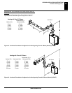
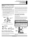
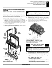
Variable
Fan Switch
Fan Switch
(N.O.)
On
Off
1
2
Black
Green
White
110/115
V.A.C.
Blower
Motor
Black
Blue
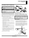
Figure 38 - Blower Wiring Diagram for Thermostatic-Controlled Models
Blower Wiring Diagram
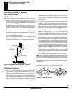
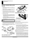
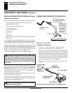
Millivolt Ignition Wiring Diagram
MILLIVOLT WIRING SCHEME
SUPPLY
INCOMING
MAIN GAS
PILOT SAFETY VALVE
N
O
T
O
L
I
P
F
F
O
TO PILOT
SAFETY
THERMO-
BURNER
PILOT
THERMOPILE
EXTERNAL WIRING USE ONLY CLASS 2
THERMOSTAT WIRE 18 GA. RED/WHITE
WALL SWITCH
TH
TP
TH/TP
WHITE
EQUIVALENT OR HIGHER RATING
REPLACE FACTORY WIRING WITH 105°C
RED
TO 120V
CONNECT
DO NOT
COUPLE
VALVE
WIRING DIAGRAMS
Figure 39 -
Millivolt Ignition Wiring Diagram
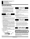
EV2
EV1
Pilot
Burner
IGNITOR LEAD
ORANGE
RED
BLACK
BLACK
BLACK
BLUE
GREEN
RED
BLUE
WHITE
BLACK
TRANSFORMER
GROUND
24 VAC
120 VAC
MODEL IS1070B
SYNETEK CONTROLS INC
GAS VALVE
Figure 40 -
Electronic Ignition Wiring Diagram
Electronic Ignition Wiring Diagram