


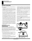
Special offers from our partners!

Find Replacement BBQ Parts for 20,308 Models. Repair your BBQ today.
12
www.desatech.com
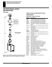
116035-01B
VENTING INSTALLATION INSTRUCTIONS
Installation Planning (Cont.)
VENTING INSTALLATION
INSTRUCTIONS
Continued
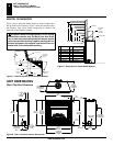
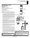
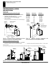
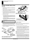
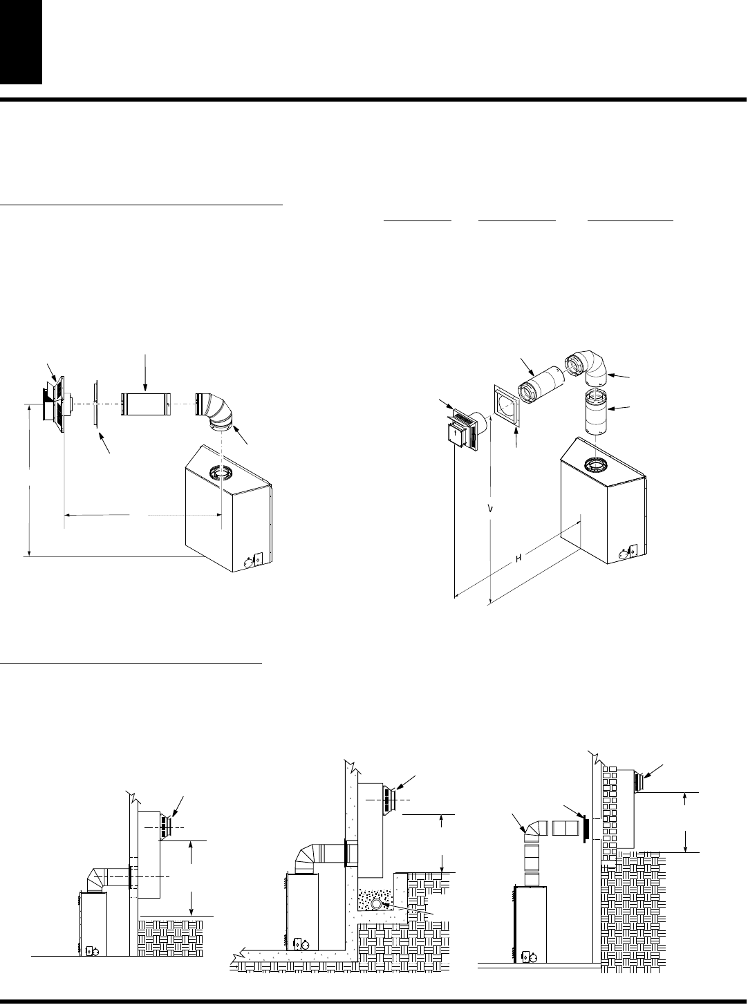
GROUND FLOOR INSTALLATION TOP VENT
Recommended Applications for Top Vent Model (V)CD36T:
• Installation using cabinet surrounds
• Through the wall using round or square termination
(up to a maximum of 24” of horizontal pipe)
• Corner installation
(Using one 90° elbow and a maximum of 24” of horizontal pipe).
TOH
90° Elbow
As Required for (V)
See Chart for Pipe
Section
Required
Square
Termination
Wall
Firestop
Not to Exceed
(H) Limits
Horizontal
Square
Termination
Wall
Firestop
Straight / Adjustable
Pipe 24" Max.
H
V
Corner Installation
Vertical (V) Horizontal (H)
45 ½“ 32 ½“
90°
Elbow
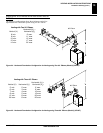
Figure 21 - Horizontal Termination Configuration for Corner
Installation using One 90° Elbow (Model (V)CD36T)
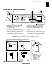
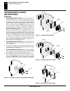
Figure 22 - Horizontal Termination Configuration with
Vertical Rise and One 90° Elbow (Model (V)CD36T)
Required Vertical (V) Allowable
Vertical (V) Vertical Pipe Horizontal (H)
45 ½” None 26” Max.
57 ¼” Min. 1 ft. 30” Max.
69 ¼” Min. 2 ft. 74” Max.
81 ½” Min. 3 ft. 98” Max.
94” Min. 4 ft. 122” Max.
106” Min. 5 ft. 146” Max.
159” Min. 9 ft. 20’ Max.
Snorkel
Terminatio
n
12"
Minimum
Snorkel
Terminatio
n
Wall
Firestop
90°
Elbow
12"
Minimum
12"
Minimum
Snorkel
Termination
Adequate
Drainage
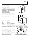
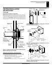
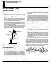
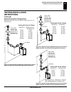
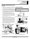
SNORKEL TERMINATION INSTALLATION
Recommended Applications Models (V)CD36R and (V)CD36T:
• Installations requiring vertical rise on building exterior. • Installation using snorkel termination to achieve 1 ft. above grade.
Snorkel terminati
you must provide proper drainage to prevent water from entering snorkel (see Figure 23). Do not back fill around snorkel termination.
Figure 23 - Snorkel Termination Configurations for Below Ground Installation