


Special offers from our partners!

Find Replacement BBQ Parts for 20,308 Models. Repair your BBQ today.
6
www.desatech.com
116035-01B
7 5/8" (194 mm)
TO CENTER OF
8" TOP VENT
14 3/4"
(375 mm)
TO NAILING
FLANGES
5/8"
(16 mm)
36"
(914 mm)
FACE DIM.
36 1/4"
(921 mm)
FACE DIM.
15 3/8"
(390 mm)
35 3/4"
(908 mm)
2.0 "
(51 mm)
25" (635 mm)
TO CENTER OF
8" REAR VENT
37" (940 mm)
TO NAILING
FLANGE
4 1/2"
(114 mm)
ELECTRICAL
INLET
8" (203 mm)
GAS SUPPLY
INLET
36 3/4"
(934 mm)
36 1/4"
(921 mm)
TO NAILING
FLANGE
2.0"
(51 mm)
2.0"
(51 mm)
38"
(965 mm)
4"
(102 mm)
TO
NAILING
FLANGE
WALL SWITCH
WIREWAY
WALL SWITCH
WIREWAY
2.5 "
(63.5 mm)
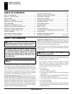
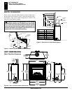
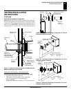
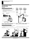
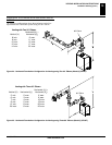
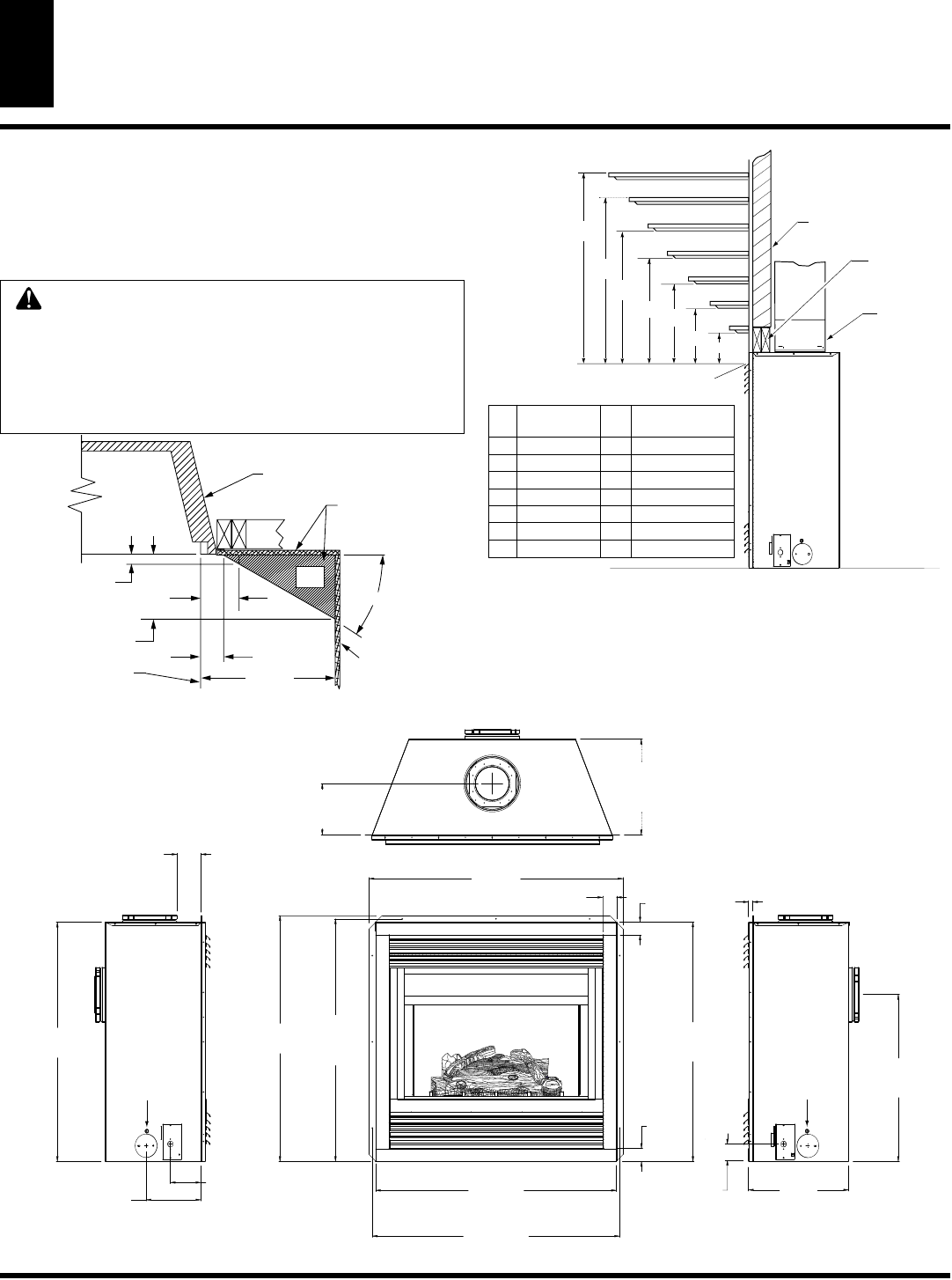
UNIT DIMENSIONS
Rear / Top Vent Common
Figure 9 - Rear / Top Vent Common Dimensions
UNIT DIMENSIONS
REAR / TOP VENT COMMON
CD36R, CD36T, VCD36R and VCD36T
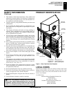
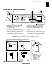
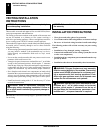
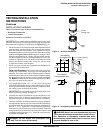
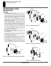
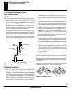
MANTEL CLEARANCES
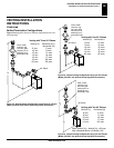
Figure 8 shows projected mantel depths at various heights above
the top of the louver opening. Figure 7 shows
the minimum allow-
able distances from various mantel components in relation to the
both sides of the fireplace opening.
C
B
A
D
E
F
G
Top of Louver Opening
3
2
1
4
5
6
7
Stud Wall
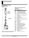
Ref. Mantel Depth Ref. Mantel from Top
of Louver Openin
g
5/8 Flue Pipe
2x Vertical
Header
@ 1” Min.
Clearance
7 2” (38mm) G 2” (51mm)
6 4” (76mm) F 4” (102mm)
5 8” (114mm) E 6” (152mm)
4 10” (152mm) D 8” (203mm)
3 12” (190mm) C 10” (254mm)
2 14” (229mm) B 12” (51mm)
1 16” (267mm) A 14” (51mm)
Figure 8 - Clearances for Combustible Mantels
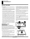
WARNING: When finishing appliance, do not overlap
combustible materials onto the black front face. Brick,
tile, or other non-combustible materials may be applied
to the face provided that any fireplace openings are not
blocked and gaps in the material used and the face are
sealed with a non-combustible caulking.
33°
SAFE
ZONE
1 1/2”
(38 mm)
3 3/4”
(95 mm)
6.0”
(152 mm)
5 1/2”
(140 mm)
12”
(305 mm)
Perpendicular
Side Wall
Combustible
Material May
Be Used
Outer Surround
To Fireplace
Opening
Figure 7 - Side Clearances for Combustible Mantels