


Special offers from our partners!

Find Replacement BBQ Parts for 20,308 Models. Repair your BBQ today.
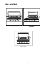
13
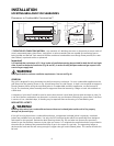
Connection: 1/2" NPT male with a 3/8" Flare adapter (included). LP Hose with a quick disconnect and fittings are
included. Operating pressure: 11.0" W.C.
CAUTION!
Before connecting LP tank to regulator, check that all grill burners and side burners, smokers, and rotisserie valves
are in the OFF position and open grill lid.
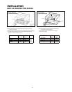
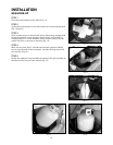
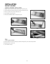
To connect the LP regulator/hose assembly to the tank/valve assembly, first make sure the main valve on the
tank is completely closed. Although the flow of gas is stopped when the Type 1 system is disconnected as part
of of its safety feature, you should always turn off the LP tank main valve (Fig. 09) after each use and during
transport of the tank or unit. Insert the regulator inlet into the tank valve and turn to the black coupler
clockwise until the coupler tightens up.
Do not overtighten the coupler. Turn the main tank valve on and turn
the burner control valves on the unit to the “HI” position for about 20 seconds to allow the air in the system to
purge, turn valves off and wait 5 minutes before attempting to light the burners.
To disconnect the coupler, first make sure the main tank valve is turned off. Grasp the coupler and turn counter
clockwise. The inlet will then disengage. Remove the inlet from the tank valve opening if it has not already
done so when it disengaged. Your local LP filling station should be equipped with the proper equipment to fill
your tank.
LP TANK REQUIREMENTS:
A dented or rusty LP tank may be hazardous and should be checked by your LP supplier. The cylinder that is
used must have a collar to protect the cylinder valve. Never use a cylinder with a damaged valve. Always
check for leaks after every LP tank change. The LP gas cylinder must be constructed and marked in accordance
with the specifications for LP gas cylinders of the U.S. Department of Transportation (DOT or CAN/CSA-B339)
and designed for use with a Type 1 system only. Do not change the regulator/hose assembly from that supplied
with the unit or attempt to use a Type 1 equipped regulator/hose assembly with a standard 510 POL tank/valve
assembly. The cylinder must be provided with a shut-off valve terminating in an LP gas supply cylinder valve
outlet specified, as applicable, for connection Type 1.
If the appliance is stored indoors, the cylinder must be
disconnected and removed from the appliance. Cylinders must be stored outdoors in a well-ventilated area
out of the reach of children.
Note:
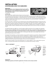
When an LP unit is being directly connected to an LP house system, you must follow the natural gas hook up guidelines.
The installer must provide the proper gas regulator to reduce the gas flow to 11” W.C.
Note:
The Grill comes with the LP Regulator/Hose assembly installed at the factory. The assembly, along with the entire Grill
system, is leak tested. Do not remove the Regulator/Hose
assembly from the Grill during installation.
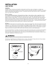
WARNING :
1. Do not remove the Grill from the pallet until you are
r
eady to install.
2. Do not place the Grill directly on the ground or any other
flat surface without support. This will prevent damaging
the r
egula
t
or/hose assembly by the weight of the grill.
3. Check the hose
, r
egula
t
or and c
onnec
t
ors f
or damage
.
Look for cracks, abrasions, brittleness, holes, dents and
nicks.
4. Do not attempt to remove, repair, or replace the
Regulator/Hose assembly by yourself. It must be done
by a qualified licensed technician only.
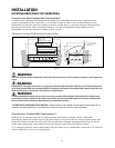
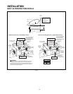
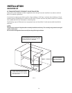
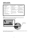
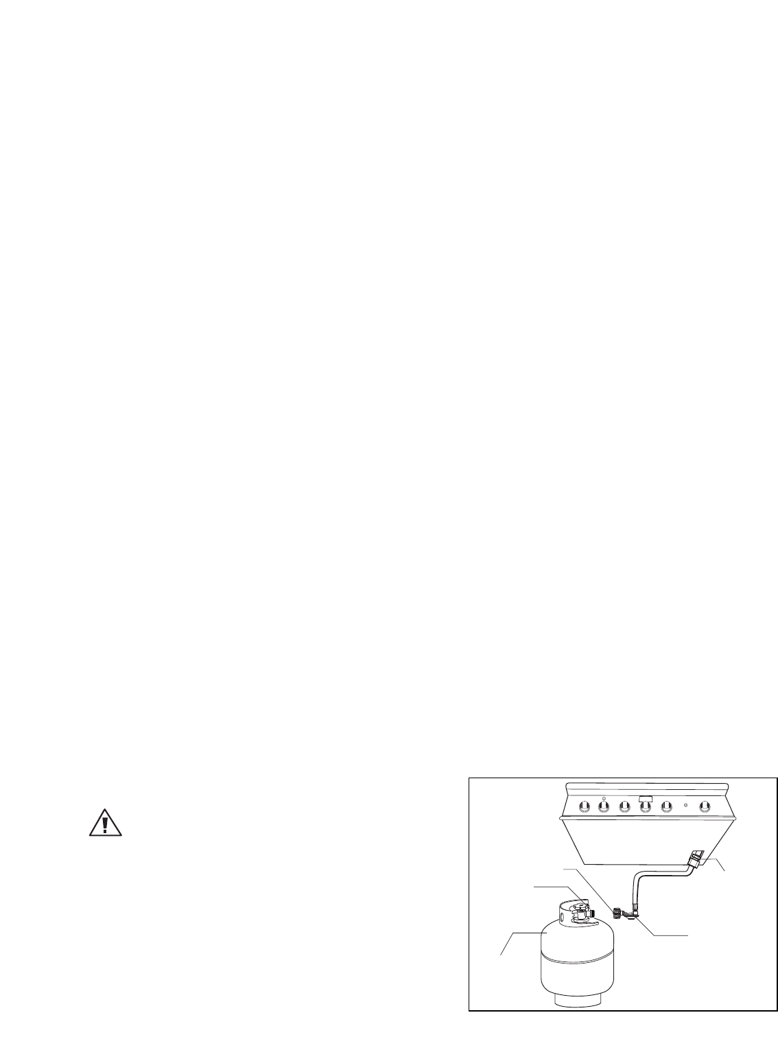
FIG. 09 LP G
as
INSTALLATION
GAS HOOK-UP
Bottom ofunit
Elbow 45
º
1/2”female
NPT x3/8”male flare
(installed onthe unit)
LP Regulator hose
assembly 11"W.C.
Type1 Regulator
MainTank Valve
20 lb. LPTank
*Installation mustconform with
local codes or with theNational
FuelGas Code ANSI Z223.1or the
CAN/CGA-B149.2Propane
Installation Code