


Special offers from our partners!

Find Replacement BBQ Parts for 20,308 Models. Repair your BBQ today.
1
t
1
]
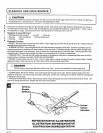
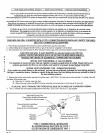
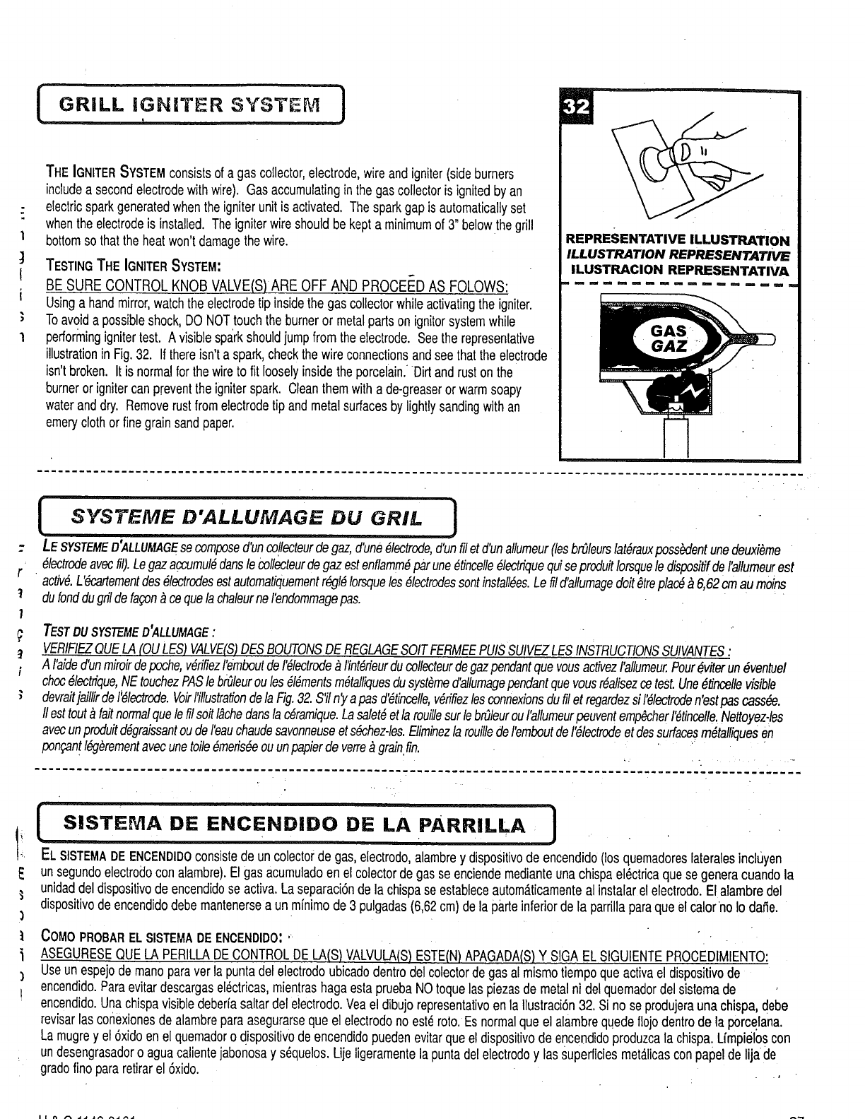
THEIGNITERSYSTEMconsistsof a gascollector,electrode,wireandigniter(sideburners
includea secondelectrodewithwire). Gasaccumulatingin thegas collectoris ignitedbyan
electricsparkgeneratedwhentheigniterunitis activated. Thesparkgapis automaticallyset
whenthe electrodeis installed. Theigniterwireshouldbe kepta minimumof 3" belowthegrill
bottomsothat the heatwon'tdamagethewire.
TESTINGTHE IGNITERSYSTEM:
BE SURE CONTROL KNOB VALVE(S) ARE OFF AND PROCEED AS FOLOWS:
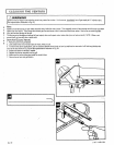
Usinga handmirror,watchthe electrodetip insidethegas collectorwhile activatingthe igniter.
Toavoida possibleshock,DO NOTtouchtheburneror metalpartson ignitorsystemwhile
performingignitertest. Avisiblesparkshouldjumpfromthe electrode.Seethe representative
illustrationin Fig.32. If thereisn'ta spark,checkthe wireconnectionsandsee thattheelectrode
isn'tbroken. It is normalfor thewireto fit looselyinsidethe porcelain.Dirt and ruston the
burneror ignitercanpreventthe igniterspark. Cleanthemwith a de-greaserorwarmsoapy
wateranddry. Removerustfromelectrodetip andmetalsurfacesbylightlysandingwithan
emeryclothor finegrainsandpaper.
REPRESENTATIVE ILLUSTRATION
ILLUSTRATION REPRESENTATIVE
ILUSTRACION REPRESENTATIVA
I mm ml mm mm mm m mm n mm m mm mm a mm mm m
r_
!
1
t
t
i
SYSTEME D'ALLUMAGE DU GRIL ]
LESYSTEMED'ALLUMAGEsecomposed'uncollecteur,degaz,d'une61ectrode,d'unfilet d'unallumeur(lesbr_leurslat_rauxposs_dentunedeuxi_me
• _lec!r_eavecill).Legazaccumul_danslecollecteurdegazestenflamm_parune_Uncelle61ectfiquequiseproduit!orsqueledispositifdeI'allumeurest
ac_6. L'_;artementdes_lectrodesestautomatiquementr_l_ Iorsqueles61ectrodessontinstall_es.Lefil d'a!lumagedolt_trepla_ _ 6,62cmaumoins
dufonddugrildefagon_cequelachaleurne rendommagepas.
TESTDUSYSTEMED'ALLUMAGE"
VERIFIEZQUELA(OULES)VALVE(S)DESBOUTONSDEREGLAGESOITFERMEEPUISSUIVEZLESINSTRUCTIONSSUIVANTES"
A I'aided'unmiroirdepoche,v_fifiezremboutder_lectrode_ fint6rieurducollecteurdegazpendantquevousactivezI'allumeur.Pour_viterun_ventuel
choc_lectrique,NEtouchezPASlebi_leuroules_16mentsm_talliquesdusyst_med'allumagependantquevousr6alisezcetest.Une_b'ncellevisible
devraltjaillirdeI'_lectrode.VoirI'illustrationdelaFig.32.S'ilny apasd_tincelle,v_rifiezlesconnexionsdufiletregardezsi r61ectroden'estpascass_e.
IIesttout_ faitnormalquelefilsoitI&chedansla c_ramique.Lasalet_etlarouillesurlebr_leurouI'allumeurpeuventemp_herr6tincelle.Nettoyezqes
V * * • t
a ecunproduitd6gralssantoudeleauchaudesavonneuseets_chez-les.EliminezlarouilledeI'emboutde1'61ectrodeetdessurfacesm_talliquesen
pon£.an!I@_rementavecunetoile_efis_e ouunpapierdeverre_ grainfin. " :
!
LA
[ SISTEMA DiE ENCENDIDO DE pARRILLA ] , .
EL SlSTEMADEENCENDIDOconsistede uncolectorde gas,electrodo,alambrey dispositivode encendido(losquemadoreslateralesincluyen
unsegundoelectrodoconalambre).Elgas acumuladoen elcolectorde gasse enciendemedianteunachispael_ctricaque segeneracuandola
unidaddel dispositivode encendidoseactiva.Laseparaci6nde lachispaseestableceautom_.ticamenteal instalarel electrodo.El alambredel
dispositivodeencendidodebernantenersea un minimode 3 pulgadas(6,62cm)de la parteinferiorde la parrillaparaque elcalorno Io dafie.
COMOPROBARELSISTEMADEENCENDIDO:'
ASEGURESEQUELA PERILLADECONTROLDE LA(S)VALVULA(S)ESTE(N)APAGADA(S)Y SIGAELSIGUIENTEPROCEDIMIENTO:
Useun espejode manoparaver la puntadelelectrodoubicadodentrodel colectordegas al mismotiempoque activael dispositivode
encendido.Paraevitardescargasel_ctficas,mientrashagaestapruebaNOtoquelaspiezasde metalni delquemadordelsistemade
encendido.Unachispavisibledeberiasaltardel eiectrodo.Veael dibujorepresentativoen la Ilustraci6n32. Si no seprodujeraunachispa, debe
revisarlasconexionesde alambreparaasegurarsequeel electrodonoest6roto.Es normalque el alambrequedeflojodentrode la porcelana.
Lamugrey el 6xidoen el quemadoro dispositiv0de encendidopuedenevitarquee!dispositivode encendidoproduzcala chispa.Limpieloscon
undesengrasadoro aguacalientejabonosay s_quelos.Lijeligeramentela puntadelelectrodoy las Superficiesmet_,licascon papelde lijade
gradofinopararetirarel 6xido.