


Special offers from our partners!

Find Replacement BBQ Parts for 20,308 Models. Repair your BBQ today.

Barbecue Owner’s Manual
Assembly and Installation
www.calspas.com
cables are tucked gently into each end of the canopy support posts. DO NOT let the canopy support posts
and canopy support post mounts pinch the cables. If this happens, the cables will be cut and will have to
be replaced.
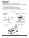
Audio/ Video (A/V) Cables
There will be two connection points for the A/V cables: one at the top of the canopy support post and one
at the bottom of the canopy support post. These cables will be stuffed into each end of the canopy support
post.
The A/V cables control the television. They are marked as follows:
Yellow for video
Red for right audio
White for left audio.
Run the A/V cables from the television up through the junction box (located on top of the canopy).
Plug the A/V cables coming from the television into a set of longer cables. Color match the cables: red to
red, white to white and yellow to yellow.
Feed each set of A/V cables down (inside) the outside canopy support posts of the canopy .
Be sure that each cable is securely attached. If not, the quality of the picture and volume will be affected.
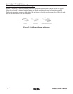
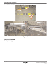
Lights
The 3-position (male) connector has 3 metal prongs at the end of it. These prongs fit into the female
receptacle of the other connector. Match up the 3-position wire (female) with the 3-position wire (male)
and securely attach them together. This step must be repeated for each main support post.
Antenna
Match up the coaxial end (female) with the other coaxial end (male) and securely attach them together.
Run the single antenna coaxial cable into the 3-way splitter (located under the grill of the G3000 Island/
Sports Bar itself).
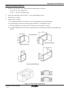
Canopy Assembly
The following instructions will allow you to assembly the canopy section of the G3000 Island/ Sports
Canopy.
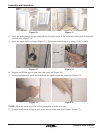
1. Lay the two triangle-shaped canopy pieces on a flat and level surface, with the support sleeves facing
up.
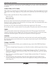
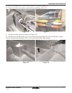
2. Place the “U” channel in between the two triangle-shaped end pieces with the “U” channel facing
inward. Line up the holes and bolt into place (Figure 24A and 24B). Repeat this step for the opposite
end of the “U” channel.
3. Repeat this process with all three support “U” channels. Make sure that all three “U” channels are
facing inward.
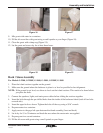
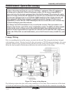
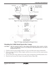
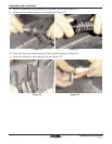
4. After making all the wire connections, slide each canopy support post into the support sleeves
(located on the canopy). Gently tuck the cables into the support post, making sure not to pinch the
cables (Figure 25).
Page 20
12/17/04