


Special offers from our partners!

Find Replacement BBQ Parts for 20,308 Models. Repair your BBQ today.
8
106497
DIRECT-VENT FIREPLACE
®
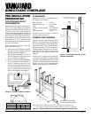
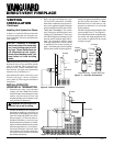
INSTALLATION FOR
HORIZONTAL TERMINATION
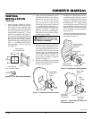
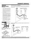
1. Determine the route your horizontal
venting will take.
Note:
The location
of the horizontal vent termination on the
exterior wall must meet all local and
national building codes and must not be
easily blocked or obstructed.
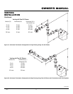
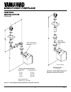
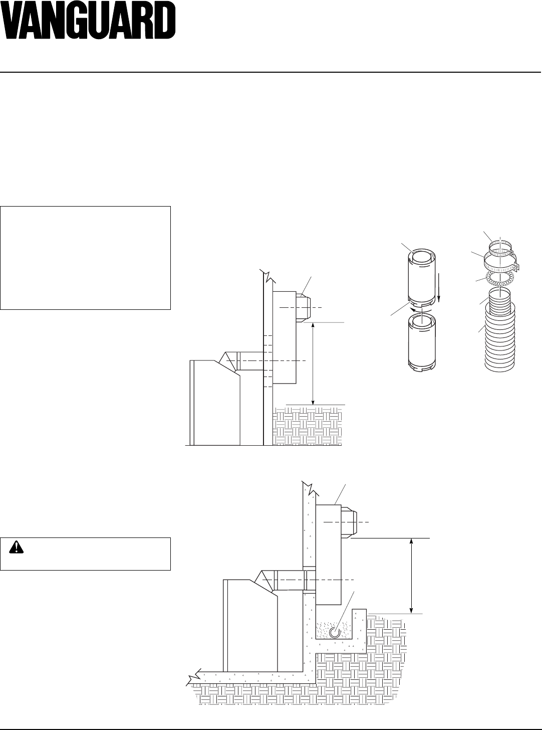
Snorkel terminations are available for
terminations requiring a vertical rise on
the exterior of the building (see Figures
9 and 10). Snorkel kit SVK is also avail-
able (see page 15). Follow the same in-
stallation procedures as used for stan-
dard horizontal terminations. If install-
ing the snorkel termination below grade
(basement applications), you must pro-
vide proper drainage to prevent water
from entering the snorkel termination
(see Figure 10). Do not back fill around
the snorkel termination.
VENTING
INSTALLATION
Continued
Figure 10 - Snorkel Termination with Drainage Pipe
Figure 9 - Snorkel Termination
WARNING: Do not recess vent
terminal into a wall or siding.
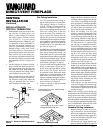
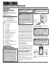
Figure 11 - Vent Pipe Connections
Female
Locking
Lugs
Male
Slots
Rigid Vent Pipe Flexible Vent Pipe
Spacer
Spring
4" Clamp
7" Clamp
4" Flex
Pipe
7" Flex
Pipe
Adequate
Drainage
12" Minimum
Snorkel
Snorkel
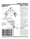
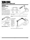
NOTICE: Treatment of firestops
and construction of the chase may
vary from building type to build-
ing type. These instructions are
not substitutes for the require-
ments of local building codes. You
must follow all local building
codes .
Note:
When installing in a chase, you should
insulate the chase as you would the outside
walls of your home. This is especially im-
portant in cold climates. Minimum clear-
ance between vent pipes and combustible
materials such as insulation is 1".
After framing the chase (see Framing and
Finishing on pages 4 and 5) install the
vent system by following the installation
instructions.
Installing Vent System in a Chase
A chase is a vertical boxlike structure built
to enclose venting that runs along the out-
side of a building. A chase is not required for
such venting.
2. Rigid vent pipes and fittings have spe-
cial twist-lock connections. Assemble
the desired combination of pipe and el-
bows to the appliance adaptor with pipe
seams oriented towards the wall or floor.
Twist-lock Procedure: The female
ends of the pipes and fittings have four
locking lugs (indentations). These lugs
will slide straight into matching slots on
the male ends of adjacent pipes and fit-
tings. (All connections must be sealed
with high temperature silicone sealant
as specified in the second warning on
page 7.) Push the pipe sections together
and twist one section clockwise approxi-
mately one-quarter turn until the sections
are fully locked. See Figure 11.
Note:
Horizontal runs of vent must be sup-
ported every three feet. Use wall straps
for this purpose.
Flexible vent pipe must be installed with
spacer springs every 12". See Figure 11.
All connections must be clamped tightly
and sealed with high temperature sili-
cone sealant as specified in the second
warning on page 7.
12"
Minimum