


Special offers from our partners!

Find Replacement BBQ Parts for 20,308 Models. Repair your BBQ today.
29
106497
OWNER’S MANUAL
BEFORE YOU BEGIN
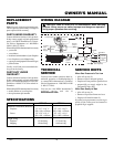
The conversion parts are packaged with the
fireplace. Please check the contents before
beginning this conversion. Each model in-
cludes a brass main burner orifice and a
smaller sized pilot orifice (see Figure 60).
Before proceeding, make sure the gas con-
trol valve is in the “OFF” position, all elec-
trical power to the appliance is OFF, and the
appliance is cool to the touch.
WARNING: This conversion
kit must be installed by a quali-
fied service agency in accordance
with the manufacturer instruc-
tions and all applicable codes
and requirements of the author-
ity having jurisdiction. If the in-
formation in these instructions is
not followed exactly, a fire, ex-
plosion, or production of carbon
monoxide may result causing
property damage, personal injury,
or loss of life. The qualified ser-
vice agency is responsible for
the proper installation of this kit.
The installation is not proper and
complete until the operation of
the converted appliance is
checked as specified in the
manufacturer’s instructions sup-
plied with the kit.
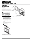
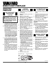
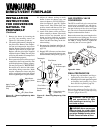
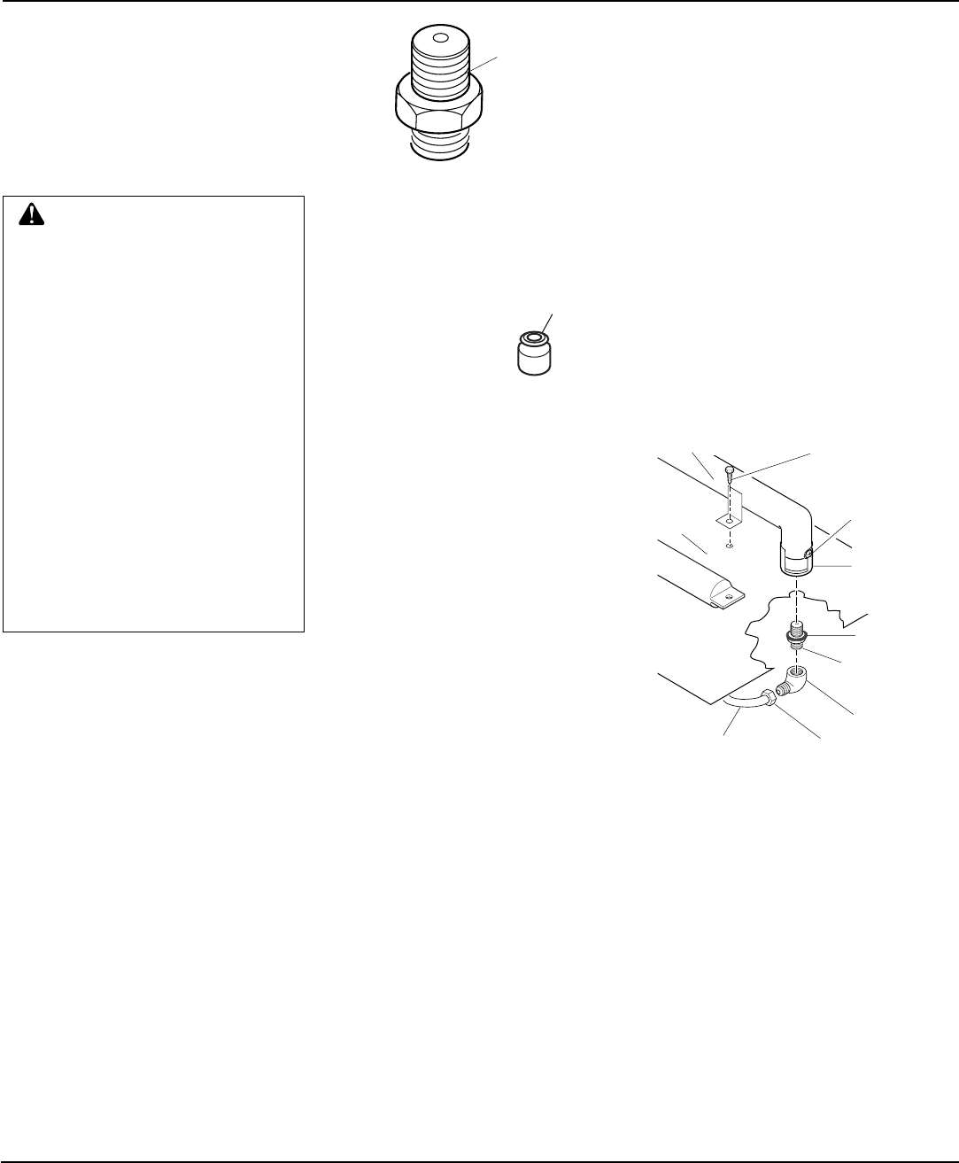
Propane/LP
Main Burner
Orifice (18mm
Hex)
Propane/LP
Pilot Orifice
Note:
The pilot orifice has
the number 30 stamped
on it for identification
purposes (Both Models).
Figure 60 - Main Burner Orifice and Pilot
Orifice
Note:
For Model MBDV37 - #55 Drill Size
(Stamped with #132 for Identification)
For Model MBDV41 - #54 Drill Size
(Stamped with #139 for Identification)
Continued
INSTALLATION
INSTRUCTIONS
FOR CONVERSION
NATURAL TO
PROPANE/LP
BURNER AIR SHUTTER
ADJUSTMENT, MAIN
BURNER ORIFICE, AND
PILOT ORIFICE
CONVERSION
1. Remove the upper louver panel and
glass door (see Removing/Replacing
Glass Door, page 22).
2. Carefully remove the log set and em-
ber material from around the burner and
place them outside the fireplace (see
Installing Logs, Lava Rock and Glow-
ing Embers, page 24).
3. Open lower louver panel. This allows
access below firebox to gas line con-
nections and gas control valve.
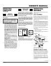
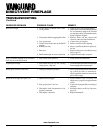
4. Disconnect flare fitting connected to the
brass elbow inside the bottom control
compartment area. Use a 3/4" open end
wrench on the flare fitting (see Figure 61).
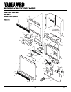
5. Turn brass elbow and main burner ori-
fice counterclockwise to remove from
burner. The orifice is threaded into the
burner inlet. The elbow may have a
slight resistance since the orifice has
been sealed with RTV silicone. Use a
7/8" open end wrench or channel lock
pliers for elbow and orifice removal.
6. Remove existing main burner orifice
from brass elbow and replace with main
burner orifice supplied with the fire-
place.
Note:
The new main burner ori-
fice for propane/LP will have the num-
ber 132 (Model MBDV37 only) or the
number 139 (Model MBDV41 only)
stamped on it for identification pur-
poses. Apply a small amount of thread
sealant to the orifice before tightening
(see Figure 62, page 30). Sealant must
be resistant to Propane/LP gas.
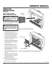
Fireplace
Floor
Burner
Main Burner
Orifice
RTV Silicone
Brass Elbow
Flare FittingAluminum Tubing
Figure 61 - Removing/Replacing Main
Burner Orifice, Brass Elbow, and Alumi-
num Tubing
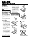
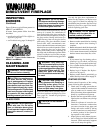
5/16" hex
Mounting Screw
Air Shutter Screw
Air Shutter
(Shown in
FULLY OPEN
Position)