


Special offers from our partners!

Find Replacement BBQ Parts for 20,308 Models. Repair your BBQ today.
6
106497
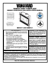
DIRECT-VENT FIREPLACE
®
Fixed
Closed
Openable
Fixed
Closed
Openable
V
V
V
V
V
V
V
V
X
X
V
X
G
G
J
F
B
B
K
N
H
I
A
N
E
L
D
B
M
A
C
B
V
V
A
G
G
B
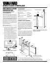
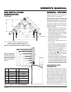
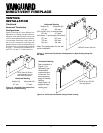
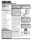
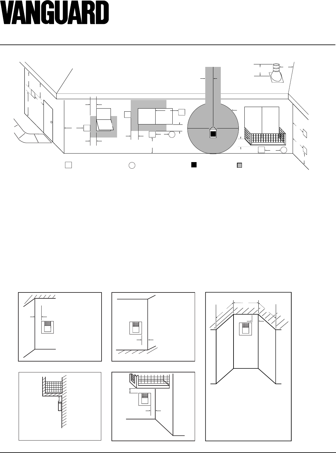
TERMINATION CAP
AIR SUPPLY INLET
GAS METER RESTRICTED AREA
(TERMINATION PROHIBITED)
A = clearance above grade, veranda, porch, deck, or balcony
[*12 inches (305mm) minimum]
B = clearance to window or door that may be opened
[12 inches (305mm) minimum]
C = clearance to permanently closed window [minimum 12 inches
(305mm) recommended to prevent condensation on window]
D = vertical clearance to ventilated soffit located above the terminal
within a horizontal distance of 24 inches (610mm) from the
center-line of the terminal [18 inches (457mm) minimum]
E = clearance to unventilated soffit [12 inches (305mm) minimum]
F = clearance to outside corner (see below)
G = clearance to inside corner (see below)
H = *not to be installed above a meter/regulator assembly within
36 inches (914mm) horizontally from the center-line of the regulator
I = clearance to service regulator vent outlet [*72 inches (1829mm)
minimum]
J = clearance to non-mechanical air supply inlet to building or the
combustion air inlet to any other fireplace [*12 inches (305mm)
minimum]
K = clearance to a mechanical air supply inlet [*72 inches (1829mm)
minimum]
L = † clearance above paved side-walk or a paved driveway located on
public property [*84 inches (2133mm) minimum]
M = clearance under veranda, porch, deck [*12 inches (305mm) minimum ‡]
N = clearance above a roof shall extend a minimum of 24 inches (610mm)
above the highest point when it passes through the roof surface and
any other obstruction within a horizontal distance of 18 inches (457mm)
† vent shall not terminate directly above a side-walk or paved driveway which is located between two
single family dwellings and serves both dwellings*
‡ only permitted if veranda, porch, deck or balconey is fully open on a minimum of 2 sides beneath the floor*
* as specified in CAN/SGA B149 (.1 or .2) Installation Codes (1991) for Canada or for U.S.A. installation follow
the current
National Fuel Gas Code, ANS Z223.1
Note: Local codes or regulations may require different clearances
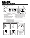
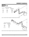
A = 6" (152mm)
Inside Corner
V
B
E
V
B = 6" (152mm)
C = Maximum depth of 48" (1219mm) for
recessed location
D = Minimum width for back wall of
recessed location -
Combustible - 38" (965mm)
Noncombustible - 24" (610mm)
E = Clearance from corner in
recessed location-
Combustible - 6" (152mm)
Noncombustible - 2" (51mm)
Outside Corner Recessed Location
G
H
G = Combustible 24" (610mm)
Noncombustible 18" (457mm)
Balcony with No Side Wall
V
J
Combustible &
Noncombustible
H = 24" (610mm)
J = 20" (508mm)
Balcony with Perpendicular Side Wall
C
D
C
Termination Clearances for Buildings with Combustible and Noncombustible Exteriors
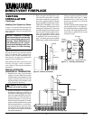
Figure 8 - Minimum Clearances for Vent Terminations
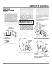
GENERAL VENTING
Continued