


Special offers from our partners!

Find Replacement BBQ Parts for 20,308 Models. Repair your BBQ today.
16
106497
DIRECT-VENT FIREPLACE
®
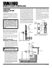
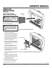
CHECK GAS TYPE
Use proper gas type for the fireplace unit
you are installing. If you have conflicting
gas types, do not install fireplace. See dealer
where you purchased the fireplace for proper
fireplace according to your gas type.
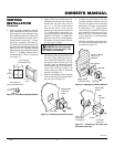
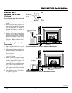
FIREPLACE
INSTALLATION
NOTICE: This heater is intended
for use as supplemental heat. Use
this heater along with your pri-
mary heating system. Do not in-
stall this heater as your primary
heat source. If you have a central
heating system, you may run
system’s circulating blower while
using heater. This will help circu-
late the heat throughout the
house. In the event of a power
outage, you can use this heater
as your primary heat source.
WARNING: A qualified ser-
vice person must install fireplace.
Follow all local codes.
CAUTION: This fireplace cre-
ates warm air currents. These cur-
rents move heat to wall surfaces
next to fireplace. Installing fire-
place next to vinyl or cloth wall
coverings or operating fireplace
where impurities (such as to-
bacco smoke, aromatic candles,
cleaning fluids, oil or kerosene
lamps, etc.) in the air exist, may
discolor walls.
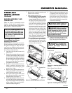
Note:
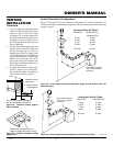
Your fireplace is designed to be used in
zero clearance installations. Wall or framing
material can be placed directly against any
exterior surface on the rear, sides, or top of
your fireplace, except where standoff spacers
are integrally attached. If standoff spacers are
attached to your fireplace, these spacers can be
placed directly against wall or framing mate-
rial. See framing details on pages 4 and 5.
Place the fireplace into position and shim
with noncombustible material if needed.
Nail the side flanges to the framing to secure
the unit in place. There are two floor brack-
ets included with each unit. Use these as an
alternative method of securing the fireplace.
IMPORTANT:
Make sure fireplace is level
before securing. If fireplace is not level it
will not work properly.
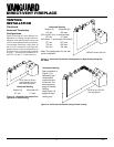
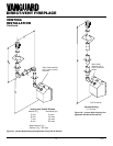
SIMPSON DURA-VENT GS
4" x 6
5
/8 "
Number Description
Available from DESA International:
SD2040 Simpson Dura-Vent GS
30° Elbow (6 pcs.)
SD2050 Simpson Dura-Vent GS
60° Elbow (6 pcs.)
Available from Simpson Dura-Vent
Only:
902 7" x 48" Pipe
903 7" x 36" Pipe
904 7" x 24" Pipe
906 7" x 12" Pipe
907 7" x 9" Pipe
908 7" x 6" Pipe
911 7" Adjustable (11"-14
5
/8") Pipe
940 Wall Thimble
941 Cathedral Ceiling Support Box
943 Roof Flashing 0/12-6/12
943S Roof Flashing 7/12-12/12
945 7" x 45° Elbow
950 Vinyl Siding Standoff
953 Storm Collar
963 Ceiling Firestop
981 36" Snorkel Termination
984 Horizontal Termination Vent Cap
988 Wall Strap
990 7" x 90° Elbow
991 Vertical High Wind Termination
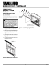
VENTING
INSTALLATION
Continued
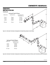
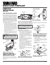
ELECTRICAL HOOKUP FOR
BLOWER ACCESSORY
Before blower accessory can be operated, it
must be properly connected to a standard
120 VAC power source. Refer to Wiring
Diagram on page 35.
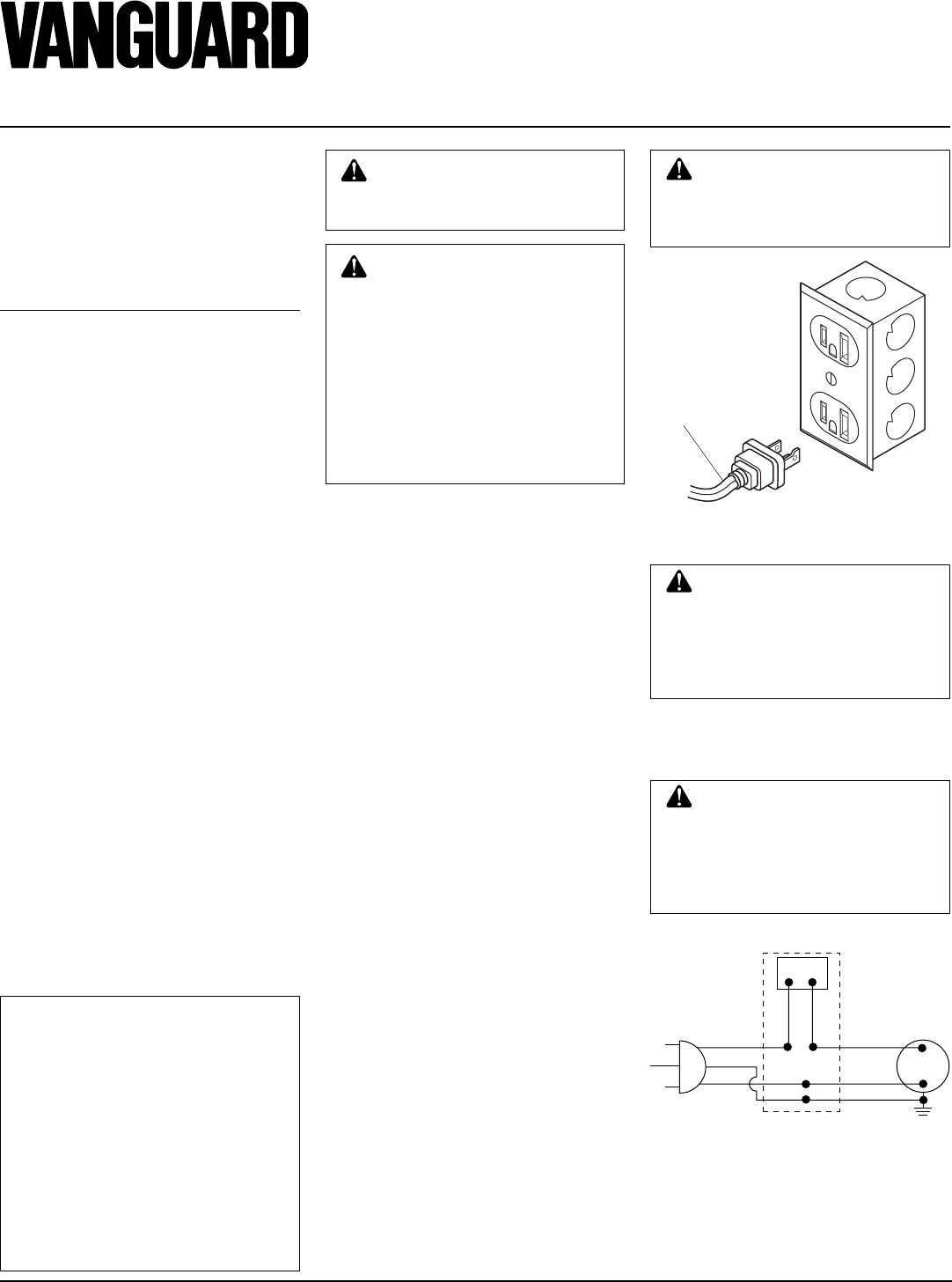
An outlet box with two receptacles has been
supplied for your convenience, located on
the lower right side of the appliance (see
Figure 29).
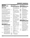
Figure 29 - Connecting Blower Acces-
sory to Power Supply
From Blower
Assembly
CAUTION: Due to high tem-
peratures, make sure no wires
are touching the bottom of the
firebox.
WARNING: Never attempt to
service heater while it is plugged
in, operating, or hot. Burns and
electrical shock could result. Only
a qualified service person should
service or repair heater.
WARNING: Label all wires
prior to disconnection when ser-
vicing controls. Wiring errors can
cause improper and dangerous
operation. Verify proper opera-
tion after servicing.
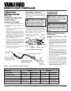
120 Vac. 60 Hz. . 78 Amps
Variable
Fan Switch
WhiteWhite
Black
Green
On
110/115
V.A.C.
Blower
Motor
Black
Black
Black
Off
If any of the original wire as supplied with
the appliance must be replaced, it must be
replaced with 105°C wire or it’s equivalent.
Figure 30 - Blower Assembly Wiring
Diagram