


Special offers from our partners!

Find Replacement BBQ Parts for 20,308 Models. Repair your BBQ today.
9
106497
OWNER’S MANUAL
UP
UP
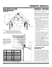
VENTING
INSTALLATION
Continued
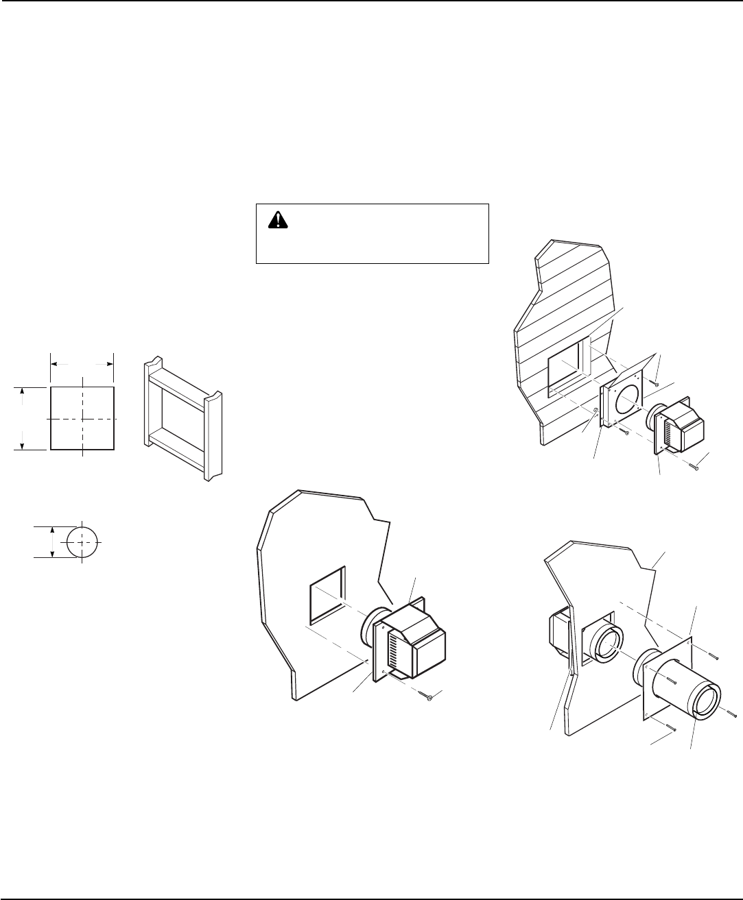
(Framing
Detail)
10"
(254mm)
10"
(254mm)
7
1
/
2
"
(190mm)
Vent Opening
Combustible Wall
Vent Opening
Noncombustible Wall
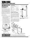
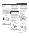
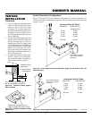
Figure 12 - Vent Opening Requirements
Continued
3. Attach vent pipe assembly to the fire-
place. Set fireplace in front of it’s perma-
nent location to insure minimum clear-
ances. Mark the wall for a 10" square hole
(for noncombustible material such as
masonry block or concrete, a 7
1
/2" diam-
eter hole is acceptable). See Figure 12.
The center of the hole should line up with
the center-line of the horizontal rigid vent
pipe. Cut a 10"x10" (254mm x 254mm)
square hole through combustible exterior
wall (7
1
/2" [190mm] diameter hole if
noncombustible). Frame as necessary
(see Figure 12).
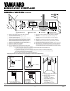
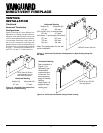
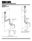
Figure 14 - Installing Vinyl Siding Standoff
Cut Vinyl Siding
Away to Fit
Standoff
Wood Screw
Nut
Bolt
Standoff
Vent Cap
Apply Mastic
to All Four Sides
Figure 13 - Installing Horizontal Vent Cap
Wood
Screw
Vent Cap
Apply Mastic
to All Four
Sides
WARNING: Do not recess vent
termination in to any wall. This
will cause a fire hazard.
4. Apply a bead of non-hardening mastic
around the outside edge of the vent cap.
Position the vent cap in the center of
the 7
1
/2" or 10" hole on the exterior
wall with the arrow on the vent cap
pointing up. Insure proper clearance of
1" to combustibles is maintained. At-
tach the vent cap with four wood screws
supplied (see Figure 13).
Note
: Re-
place the wood screws with appropri-
ate fasteners for stucco, brick, concrete,
or other types of siding.
For vinyl siding use vinyl siding stand-
offs between vent cap and exterior wall.
The vinyl siding standoff prevents ex-
cessive heat from melting the vinyl sid-
ing material. Bolt the vent cap to the
standoff. Apply non-hardening mastic
around outside edge of the standoff in-
stead of the vent cap assembly. Use
wood screws provided to attach the
standoff. See Figure 14.
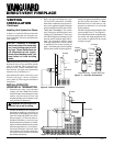
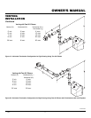
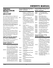
5. Slide the wall thimble over the vent pipe
before connecting the horizontal run to
the vent cap (see Figure 15).
6. Carefully move the fireplace with vent
assembly attached toward the wall and
insert the vent pipe into the horizontal
termination. The pipe overlap should
be a minimum of 1
1
/4". Apply silicone
to the outer pipe connection. Fasten all
vent connections with screws provided.
Refer to Fireplace Installation on page
16 for instructions on securing unit to
framing or floor.
7. Slide the wall thimble against the inte-
rior wall surface and attach with screws
provided (see Figure 15).
Vent Cap
(Horizontal
Termination)
Interior Wall
Surface
Wall
Thimble
Horizontal
Vent Pipe
Figure 15 - Connecting Vent Cap with
Horizontal Vent Pipe
Screw