


Special offers from our partners!

Find Replacement BBQ Parts for 20,308 Models. Repair your BBQ today.
20
106497
DIRECT-VENT FIREPLACE
®
O
F
F
P
I
L
O
T
O
N
P
I
L
O
T
EA
16AI
7
TPTH TP TH
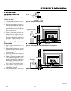
Pressure Testing Gas Supply
Piping System
Test Pressures In Excess Of 1/2 PSIG
(3.5 kPa)
1.
Disconnect fireplace and its individual
equipment shutoff valve from gas supply
piping system. Pressures in excess of 1/2
psig (3.5 kPa) will damage fireplace gas
regulator.
2. Cap off open end of gas pipe where
equipment shutoff valve was con-
nected.
3. Pressurize supply piping system by ei-
ther opening propane/LP supply tank
valve for propane/LP gas fireplace or
opening main gas valve located on or near
gas meter for natural gas fireplace,
or
using compressed air.
4. Check all joints of gas supply piping
system. Apply commercial leak test so-
lution to all gas joints. Bubbles forming
show a leak. Correct all leaks at once.
5. Reconnect fireplace and equipment
shutoff valve to gas supply. Check re-
connected fittings for leaks.
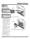
CHECKING GAS
CONNECTIONS
WARNING: Test all gas pip-
ing and connections for leaks
after installing or servicing. Cor-
rect all leaks at once.
WARNING: Never use an open
flame to check for a leak. Apply
commercial leak test solution to
all gas joints. Bubbles forming
show a leak. Correct all leaks at
once.
Installation Items Needed
• 5/16" hex socket wrench or nut-driver
• sealant (resistant to propane/LP gas, not
provided)
1. Open lower louver door panel by gen-
tly pulling forward.
2. Route flexible gas line (provided by
installer) from equipment shutoff valve
to fireplace. Route flexible gas supply
line through one of the access holes on
side of fireplace or through knockout
hole on firebox bottom.
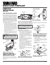
3. Attach a 45° flare union gas connector
to flexible gas line from gas supply (see
Figure 41). Connect flare union to flex-
ible gas line attached to gas regulator
of fireplace (see Figure 41).
4. Check all gas connections for leaks. See
Checking Gas Connections.
CONNECTING FIREPLACE
TO GAS SUPPLY
FIREPLACE
INSTALLATION
Continued
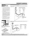
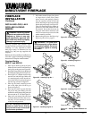
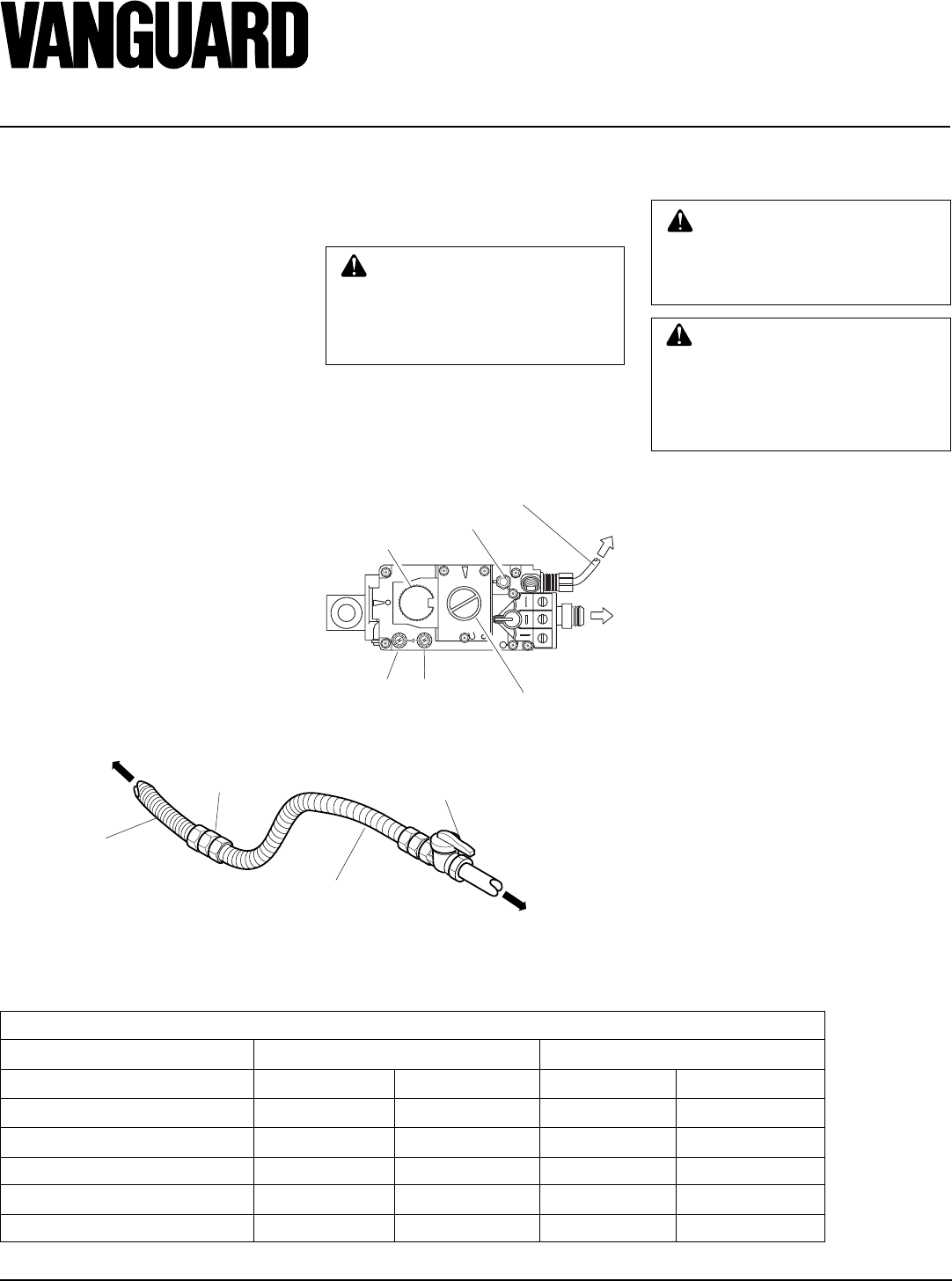
Flare Union
To Fireplace
Gas Valve
Flexible Gas Line from
Fireplace Gas Valve
Provided with Fireplace
Flexible Gas Line from
Equipment Shutoff Valve
Provided by Installer
Equipment Shutoff Valve
To Gas
Supply
(Natural)
To External
Regulator
(Propane/LP)
Figure 41 - Attaching Flexible Gas Lines Together
GAS RATING
MODEL NO. MBDV37 MBDV41
TYPE OF GAS NATURAL PROPANE/LP NATURAL PROPANE/LP
Max. Input Rating: 22,000 Btu/hr 20,000 Btu/hr 24,000 Btu/hr 22,000 Btu/hr
Orifice Size (0-4,500 Ft.): #43 #55 #42 #54
Manifold Pressure: 3.5 in. W.C. 10.0 in. W.C 3.5 in. W.C. 10.0 in. W.C.
**Minimum Supply Pressure: 4.5 in. W.C. 11.0 in. W.C. 4.5 in. W.C. 11.0 in. W.C.
**Maximum Supply Pressure: 10.5 in. W.C. 13.0 in. W.C. 10.5 in. W.C. 13.0 in. W.C.
** For the purpose of input adjustment.
GAS SUPPLY TESTING
Note:
This section is intended as a guide for
qualified service technicians installing gas
to the appliance.
CAUTION: Do not connect
appliance before pressure test-
ing gas piping. Damage to the
gas valve may result and an un-
safe condition may be caused.
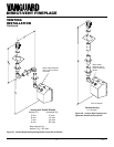
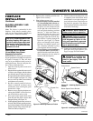
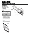
Figure 42 - Millivolt Control Valve
Pilot Gas Line - Do Not Kink
To Pilot
Burner
Pilot Adjustment Cap
ON/OFF
Knob
To Main
Burner
Conversion Screw
Outlet
Pressure
Inlet
Pressure
The gas control valve is secured underneath
the firebox with two brackets fastened to the
firebox bottom. Two pressure taps are pro-
vided on the gas control valve for a pressure
gauge connection (see Figure 42).