


Special offers from our partners!

Find Replacement BBQ Parts for 20,308 Models. Repair your BBQ today.
5
106497
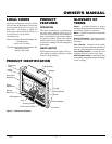
OWNER’S MANUAL
C
B
A
D
E
F
G
Top of Louver Opening
3
2
1
4
5
6
7
Wall
29"
13"
10
1
/
4
"
8
3
/
4
"
37"
41"
37
1
/
2
"
41
1
/
2
"
58"
9
1
/
4
"
41"
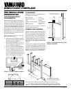
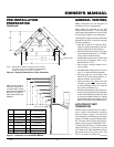
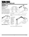
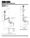
Note
: Where two numbers are given the top number
is exclusive to the 37" Fireplace and the bottom
number is exclusive to the 41" Fireplace
Nailing Tabs
PRE-INSTALLATION
PREPARATION
Continued
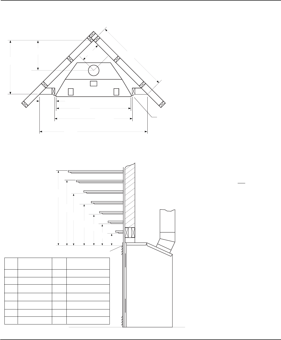
Figure 6 - Framing Clearances for Corner Installation
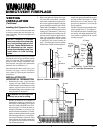
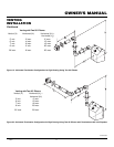
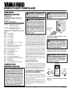
LOCATION OF VENT
TERMINATION
When locating vent termination, it is impor-
tant to observe the minimum clearances
shown in Figure 8, page 6. You will avoid
extra framing by positioning your fireplace
against an already existing framing mem-
ber. The sides of the fireplace may be posi-
tioned directly against combustible walls.
*Check with local codes or with the current
CAN/CGA B149[.1 or .2] Installation Codes
for Canada or the USA Installations follow
the current National Fuel Gas Code, ANS
Z223.1, also known as NFPA 54.
Note:
Terminations are not designed for
installation prior to transportation.
These models are approved for use with
Simpson Dura-Vent 6
5
/8" direct-vent pipe
components and terminations as well as both
flex and rigid Vanguard vent components.
Your fireplace is approved to be vented either
through the side wall, or vertically using the
following guidelines:
• Only use Vanguard or Simpson Dura-
Vent GS venting components or kits spe-
cifically approved for this fireplace.
• Minimum clearance between vent pipes
and combustible materials is 1" (25 mm),
except where stated otherwise.
• Combustible material may be flush with
the top front of fireplace with a maxi-
mum thickness of 3/4".
• Do not recess venting terminals into a
wall or siding.
• Install horizontal venting with a 1/4" rise for
every 12" of run toward the termination.
• You may paint the vent terminal with
450ºF (232ºC) heat-resistant paint to co-
ordinate with the exterior finish.
• There must not be any obstruction such
as bushes, garden sheds, fences, decks,
or utility buildings within 24" from the
front of the termination cap.
• Do not locate termination cap where exces-
sive snow or ice build up may occur. Be sure
to clear vent termination area after snow falls
to prevent accidental blockage of venting
system. When using snow blowers, do not
direct snow towards vent termination area.
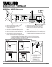
GENERAL VENTING
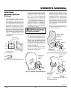
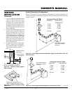
Figure 7 - Clearances for Combustible Mantels
Ref. Mantel Depth Ref. Mantel from Top
of Louver Opening
1 14" (356mm) A 16" (406mm)
2 12" (305mm) B 14" (356mm)
3 10" (254mm) C 12" (305mm)
4 8" (203mm) D 10" (254mm)
5 6" (152mm) E 8" (203mm)
6 4" (101mm) F 6" (152mm)
7 2" (51mm) G 4" (101mm)
Note:
There must be a
minimum clearance of
18" above top of louver
opening when installing a
television or entertain-
ment center above the
fireplace.
Continued