


Special offers from our partners!

Find Replacement BBQ Parts for 20,308 Models. Repair your BBQ today.
9 Model 7500 Instruction Manual
Teledyne Analytical Instruments
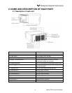
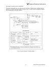
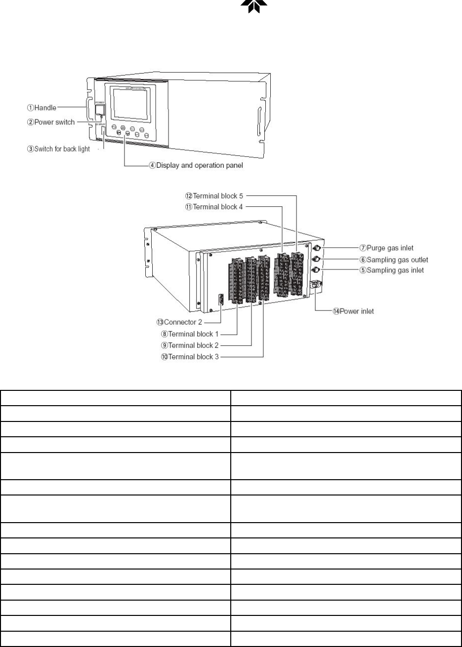
2. NAME AND DESCRIPTION OF EACH PART
2.1 Description of each unit
Name Description
1. Handle Draws the analyzer unit from the case.
2. Power switch Turns ON/OFF this analyzer.
3. Switch for back light Turn ON/OFF the back light of display.
4. Display / Operation panel Liquid crystal display and keys for various
operational settings are arranged.
5. Sampling gas inlet Port for connecting the sample gas injection pipe.
6. Sampling gas outlet Port for connecting the pipe for discharging the
gas after analysis.
7. Purge gas inlet Port for connecting the purge gas pipe.
8. Terminal block 1 Analog output terminals
9. Terminal block 2 Analog signal and contact input terminals
10. Terminal block 3 Contact output terminals
11. Terminal block 4 Contact output terminal
12. Terminal block 5 Alarm output terminal
13. Connector 2 Communication interface
14. Power inlet Used to connect the power cable.