


Special offers from our partners!

Find Replacement BBQ Parts for 20,308 Models. Repair your BBQ today.
21 Model 7500 Instruction Manual
Teledyne Analytical Instruments
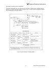
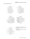
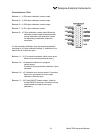
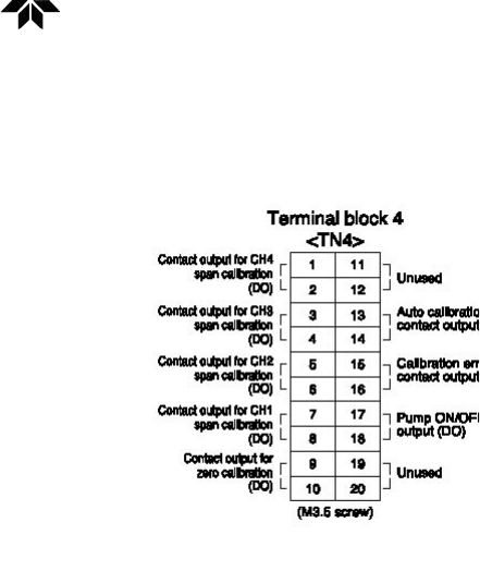
Terminal block 4 <TN4>
Between 1 – 2: CH4 span calibration contact output
Between 3 – 4: CH3 span calibration contact output
Between 5 – 6: CH2 span calibration contact output
Between 7 – 8: CH1 span calibration contact
Between 9 – 10: Zero calibration contact output When the
calibration contact output is measured with
manual calibration, the calibration contact
corresponding to calibration channel is
conductive.
For the automatic calibration, they are worked sequentially
according to “6.4 Auto calibration setting”. If calibration is not
performed, all of them are open.
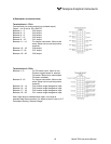
Between 11 – 12: For internal connection. Must not be wired.
(Must not be used as junction terminal.)
Between 13 – 14: Automatic calibration in progress,
contact output.
Conductive during automatic calibration. Open
otherwise.
Between 15 – 16: Calibration error contact output. Conductive
when error is produced at zero or span
calibration. Normally open.
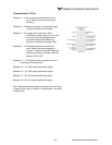
Between 17 – 18: Pump ON/OFF contact output. (Used for
turning ON/OFF the pump. Conductive during
measurement and open at zero span
calibration.)