


Special offers from our partners!

Find Replacement BBQ Parts for 20,308 Models. Repair your BBQ today.

64 Model 7500 Instruction Manual
Teledyne Analytical Instruments
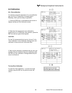
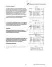
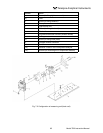
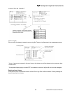
(2) How to remove block cell (See Fig. 7-2)
1. For Step 1 to 4, see Item 7.3.1, (1) How to remove pipe cell.
5. Remove the connector to the detector output cord from the printed board. For the 2-component
analyzer, remove the output cord connector of the 2-component analyzer detector (No. 13)
from the printed board, and then remove the 2-component detector by unscrewing two mounting
screws (No. 14) fastening the 2-component detector.
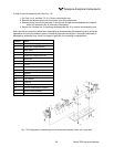
6. Unscrew the two screws (No. 10) that hold the detector to the infrared ray light source unit to
remove the detector from the measuring unit. The cell can be removed together with the detector.
7. To remove the cell, unscrew the two screws (No. 6) holding the cell to the detector. The infrared
transmission window is just sandwiched (not xed) between the detector and block cell. Keep the
detector facing up, when removing this window.
8. For assembly, reverse the disassembly procedures.
Note: The O-ring is placed between the window holder and cell. Take care about the O-ring position. With
2-component analyzer, install 2-component detector last. Take care so that no space is left between the
1-component and 2-component detectors. When inserting the detector output cord connector into the
printed board, plug the connectors for 1-component detector and 2-component detector into position. The
1-component connector should be plugged into CN11 and 2-component connector into CN1, respectively.