


Special offers from our partners!

Find Replacement BBQ Parts for 20,308 Models. Repair your BBQ today.
66 Model 7500 Instruction Manual
Teledyne Analytical Instruments
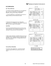
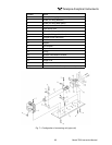
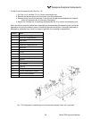
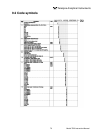
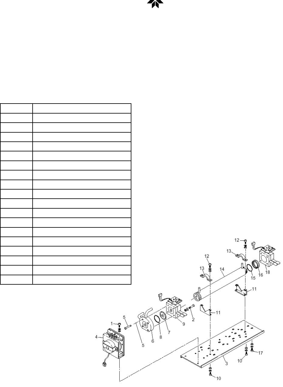
3) How to remove measuring unit (See Fig. 7-3)
1. For Step 1 to 4, see Item 7.3.1(1), How to remove pipe cell.
2. Remove the detector output cord connector from the printed board.
3. Remove wiring to the 2-pin terminals of the infrared ray light source assembly and chopper
motor pin connector (No. 8) from the printed board.
4. Detach the 4 screws (No. 3) fastening the base plate (No. 4) to remove the measuring unit.
Note: Special care should be taken when assembling or disassembling the measuring cell to avoid the
application of force to the detector pipe or infrared ray light source unit pipe. If the pipe is deformed or
damaged by excessive force, there is a danger of gas leak, thus resulting in misoperation.
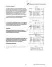
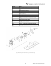
Number Name
1 Screw (for xing light source)
2 Screw (for xing detector)
3 Base plate
4 Light source unit
5 Screw (for xing block cell)
6 Block cell
7 Infrared transmission window
8 O-ring
9 Detector
10 Screw (for xing base plate)
11 Support
12 Screw (for xing cell retainer)
13 Cell retainer
14 Pipe cell
15 O-ring
16 Infrared transmission window
17 Screw (xing detector)
18 Detector
Fig. 7-3 Conguration of measuring unit (2-component analyzer: block cell + pipe cell)