


Special offers from our partners!

Find Replacement BBQ Parts for 20,308 Models. Repair your BBQ today.
68 Model 7500 Instruction Manual
Teledyne Analytical Instruments
8. TROUBLESHOOTING
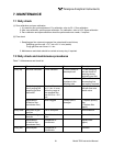
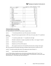
8.1 Error message
If errors occur, the following contents are displayed.
Error display Error contents Probable causes
Error No. 1 Sector motor rotation detector signal is faulty. • Infrared ray light source is faulty.
• Sector motor rotation is faulty or stopped.
• Motor rotation detector circuit is faulty.
• Amplier circuit is faulty.
Error No. 3 A/D conversion signal is faulty. • Circuit is faulty.
Error No. 4 Zero calibration is not within the allowable
range.
• Zero gas is not supplied.
• Zero point is deected much due to a dirty cell.
• Detector is faulty.
Error No. 5 A amount of zero calibration (indication value) is
over 50% of full scale.
Error No. 6 Span calibration is not within the allowable
range.
• Span gas is not supplied.
• Calibrated concentration setting does not
match cylinder concentration.
• Zero calibration is not performed properly.
• Span is deected much due to dirty cell.
• Detector sensitivity is deteriorated.
Error No. 7 A amount of span calibration (difference
between indication value and calibrated
concentration value) is over 50% of full scale.
Error No. 8 Measured values uctuate to much during zero
and span calibration.
• Calibration gas is not supplied.
• Time for supplying calibration gas is not short.
Error No. 9 Calibration is abnormal during auto calibration. • Error corresponding to No. 4 to No. 8 occurred
during auto calibration.
Error No. 10 Output cable connection is improper. • Wiring is detached between analyzer and
interface module.
• Wiring is disconnected between analyzer and
interface module.
Note: When errors No. 1, No. 3 and No. 10 occur, instrument error output contacts are conductive.
When errors No. 4 to No. 9 occur, calibration error output contacts are conductive.
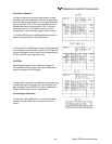
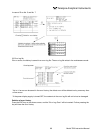
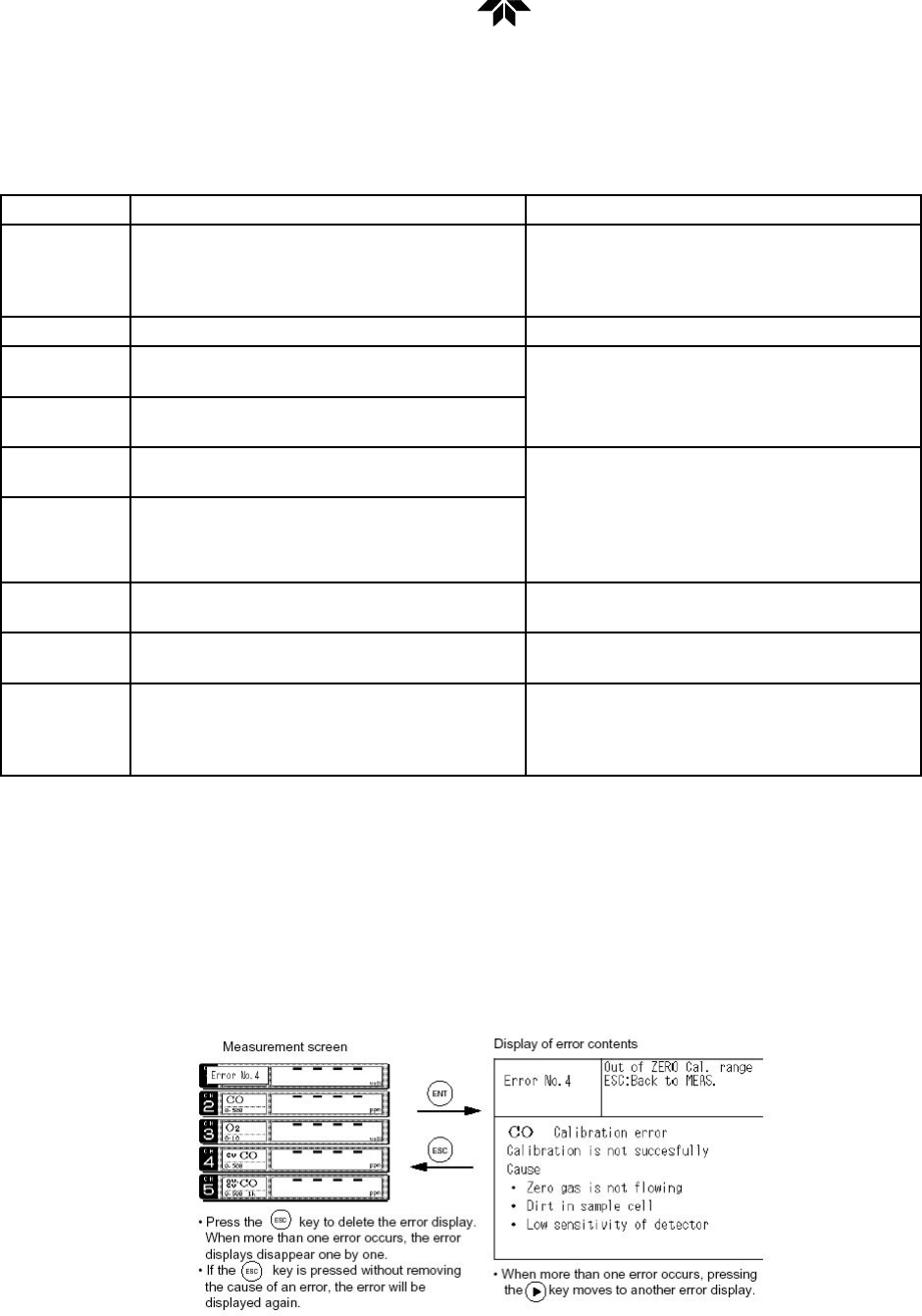
Screen display and operation at the occurrence of error.
In case of Error No. 1 to No. 4, No. 6, No. 8 to No. 10