


Special offers from our partners!

Find Replacement BBQ Parts for 20,308 Models. Repair your BBQ today.

71 Model 7500 Instruction Manual
Teledyne Analytical Instruments
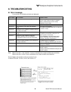
(2) Standard functions
Output signal holding:
Output signals are held during manual and auto
calibrations by activation of holding (turning on its
setting). The values to be held are the ones just before
start calibration mode. Indication values will not be held.
Remote output holding:
Output signal is held at the latest value by short-circuiting
the remote output holding input terminals. Holding
is maintained while the terminals are short-circuited.
Indication values will not be held.
Remote range changeover:
Measuring range can be changed according to an
external signal when remote range changeover input
is received. Changeover is effective only when remote
range setting is turned on. In this case, measuring range
cannot be changed manually.
When the contact input terminals for each component
are short-circuited, the rst range is selected, and it is
changed over to the second range when the terminals are
open.
Range identication signal:
The present measuring range is identied by a contact
signal. The contact output terminals for each component
are short-circuited when the rst range is selected, and
when the second range is selected, the terminals are
open.
Auto calibration:
Auto calibration is carried out periodically at the preset
cycle. When a standard gas cylinder for calibration and
a solenoid valve for opening/closing the gas ow line are
prepared externally by the customer, calibration will be
carried out with the solenoid valve drive contacts for
zero calibration and each span calibration turned on/off
sequentially at the set auto calibration timing.
Auto calibration cycle setting:
Auto calibration cycle is set. Setting is variable within 1
to 99 hours (in increments of 1 hour) or 1 to 40 days (in
increments of 1 day).
Gas ow time setting:
The time for owing each calibration gas in auto
calibration is set. Settable within 60 to 599 seconds (in
increments of 1 second)
Auto calibration remote start:
Auto calibration is carried out only once according to an
external input signal. Calibration sequence is settable in
the same way as the cyclic auto calibration. Calibration
starts when a non-voltage rectangular wave is applied to
the auto calibration remote start input terminals (opened
after short-circuiting for 1.5 seconds or longer). Auto
calibration is started when the contacts open.
Auto zero calibration:
Auto zero calibration is carried out periodically at
the preset cycle. This cycle is independent on “Auto
calibration” cycle.
When zero calibration gas and solenoid valve for
opening/closing the calibration gas ow line are prepared
externally by the customer, zero calibration will be carried
out with the solenoid valve drive contact for zero
calibration turned on/off at the set auto zero calibration
timing.
Auto zero calibration cycle setting:
Auto zero calibration cycle is set. Setting is variable
within 1 to 99 hours (in increments of 1 hour) or setting is
variable within 1 to 40 days (in increments of 1 day).
Gas ow time setting:
The timing for owing zero gas in auto zero calibration
is set. Settable 60 to 599 seconds (in increments of 1
second)
Upper/lower limit alarm:
Alarm contact output turns on when the preset upper or
lower limit alarm value is reached.
Contacts close when the instantaneous value of each
component becomes larger than the upper alarm limit
value or smaller than the lower alarm limit value.
Instrument error contact output:
Contacts close at occurrence of analyzer error No. 1, 3 or
10.
Calibration error contact output:
Contacts close at occurrence of manual or auto
calibration error (any of errors No. 4 to 9).
Auto calibration status contact outputs:
Contacts close during auto calibration.
Pump ON/OFF contact output:
During measurement, this contact close. While calibration
gas is owing, this contact open. This contact is
connected in power supply of pump, and stop the sample
gas while calibration gas owing.
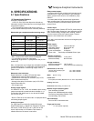
(3) Optional functions
O2 correction:
Conversion of measured CO and SO2 gas concentrations
into values at standard O2 concentration
21-On
Correction formula: C = ––––––––- x Cs
21-Os
C: Sample gas concentration after O2 correction