


Special offers from our partners!

Find Replacement BBQ Parts for 20,308 Models. Repair your BBQ today.
70 Model 7500 Instruction Manual
Teledyne Analytical Instruments
9. SPECIFICATIONS
9.1 Specications
(1) Standard specications
Principle of measurement:
CO2, CO, CH4, SO2; Non-dispersion infrared-ray
absorption method; Single light source and single beam
(single beam system)
O2: Paramagnetic method (O2 sensor built in) or
zirconia sensor method (O2 sensor externally installed)
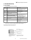
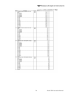
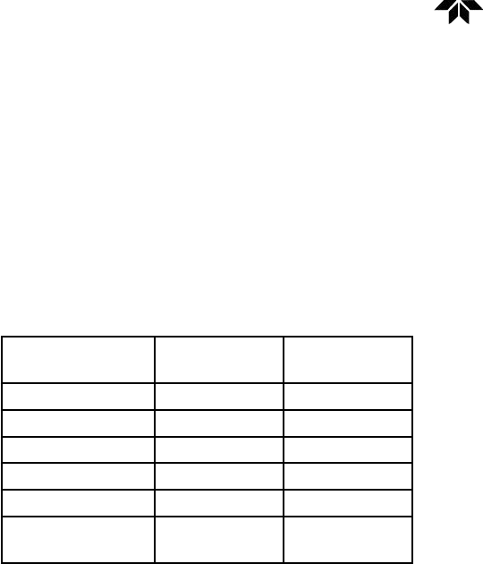
Measurable gas components and measuring range:
Minimum range Maximum
range
CO2 0 to 500 ppm 0 to 100 vol%
CO 0 to 200 ppm 0 to 100 vol%
CH4 0 to 1000 ppm 0 to 100 vol%
SO2 0 to 1000 ppm 0 to 5000 ppm
O2 (built in) 0 to 5 vol% 0 to 100 vol%
O2 (external
zirconia)
0 to 5 vol% 0 to 25 vol%
• Max. 4 components measurement including O2.
• 1 or 2 measuring range per component.
• Measuring range ratio ≤ 1:5 (except built in O2) ≤ 1:20
(built in O2)
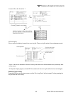
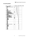
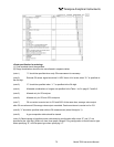
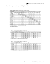
Max. 4 components and 2 ranges are selectable including
an O2 measurement. For measurable components and
possible combinations of measuring ranges, refer to
Tables 1 to 6.
Measured value indication:
Digital indication in 4 digits (LCD with back light)
• Instantaneous value of each component
• Instantaneous value after O2 correction (only in CO,
SO2 measurement with O2)
• Average value after O2 correction (only in CO, SO2
measurement with O2)
• O2 average value
Analog output signals:
4 to 20mA DC or 0 to 1V DC, non-isolated output. Analog
output corresponds to measured value indication in 1:1.
Permissible load; 550Ω max. for 4 to 20 mA DC100kΩ
min. for 0 to 1V DC
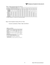
* Refer to Table 6, for the channel No. of displayed values
and analog output signals.
Analog input signal:
For signal input from externally installed O2 sensor.
Signal requirement; (1) Signal from Teledyneʼs Zirconia
O2 sensor (TYPE: ZFK7) (2) 0 to 1V DC from an O2
sensor Input section is not isolated. This feature is
effective when an O2 sensor is not built in.
Relay contact output:
1a contact (250V AC/2A, resistive load) Instrument error,
calibration error, range discrimination, auto calibration
status, solenoid valve drive for auto calibration, pump
ON/OFF.
1c contact (250V AC/2A, resistive load) Upper/lower
alarm contact output. Peak count alarm contact output.
* All relay contacts are isolated mutually and from the
internal circuit.
Contact input:
Non-voltage contact (ON/0V, OFF/5V DC, 5mA owing at
ON); Remote range changeover, auto calibration remote
start, remote holding, average value resetting; Isolated
from the internal circuit with a photocoupler. Contact
inputs are not isolated from one another.
*Only M3.5 screw terminals are used for all signal inputs
and outputs.
Power supply:
Rated voltage: 100V to 240V AC
Operating voltage: 85V to 264V AC
Rated frequency: 50/60 Hz
Power consumption: 70 VA max.
Power inlet: Conformity to EN60320 Class I type
Operation conditions:
Ambient temperature: -5°C to 45°C
Ambient humidity: 90% RH max.
Storage conditions:
Ambient temperature: -20°C to 60°C
Ambient humidity: 100% RH max.noncondensing
Dimensions (H x W x D):
19-inch rack mounting type: 177 x 483 x 493mm
Desk-top type: 194 x 483 x 493mm
Mass: Approx. 10 kg
Finish color:
Front panel; Off-white (Munsell 10Y7.5 / 0.5 or equivalent)
Casing: Steel-blue
Enclosure: Steel casing, for indoor use
Material of gas-contacting parts:
Gas inlet/outlet; SUS304
Sample cell; SUS304/neoprene rubber
Infrared-ray transmitting window; CaF2
Internal tubing; Toaron tube
Gas inlet/outlet:
Rc1/4 or NPT1/4 internal thread
Purge gas ow rate:
1 L / min (when required)