


Special offers from our partners!

Find Replacement BBQ Parts for 20,308 Models. Repair your BBQ today.
63 Model 7500 Instruction Manual
Teledyne Analytical Instruments
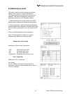
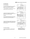
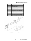
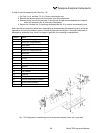
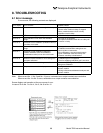
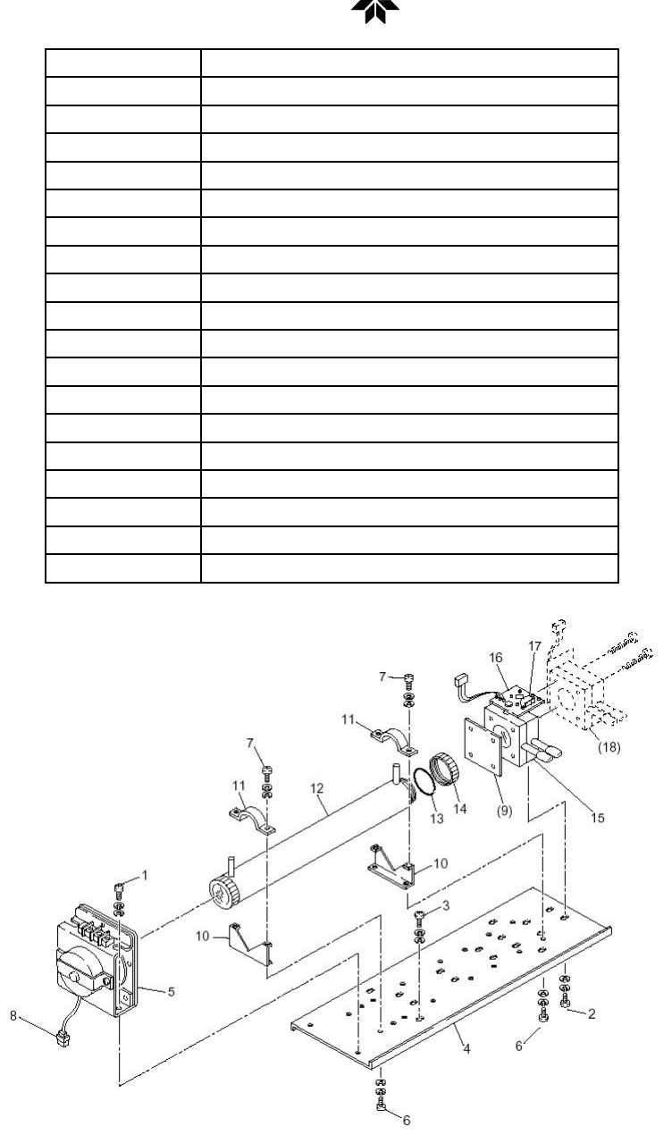
Number Name
1 Screw (for xing light source unit)
2 Screw (for xing detector)
3 Screw (for xing base plate)
4 Base plate
5 Light source unit
6 Screw (for xing support)
7 Screw (for xing cell retainer)
8 Chopper motor connector
(9) Filter
10 Support
11 Cell retainer
12 Pipe cell
13 O-ring
14 Infrared transmission window
15 Detector
16 Bridge PCB
17 Bridge resistance
(18) Detector: Installed in 2-component analyzer only
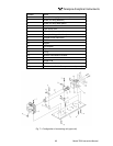
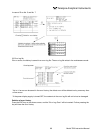
Fig. 7-1 Conguration of measuring unit (pipe cell)