


Special offers from our partners!

Find Replacement BBQ Parts for 20,308 Models. Repair your BBQ today.
1
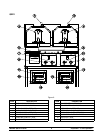
Models QS10 & QS22 To the Installer
Section 1 To the Installer
These machines are designed for indoor use
only.
DO NOT installthemachineinanarea
where a water jet could be used to clean or rinse the
machine. Failure to follow this instruction may result
in serious electrical shock.
Air Clearance
Clearances from the grill to other surfaces are
required for adequate air circulation:
Rear: 3 inches (76 mm) minimum.
Sides: 3 inches (76 mm) to combustible
surfaces;
0 inches (0 mm) to non-combustible
surfaces;
0 inches (0 mm) between grills in
multiple installations.
Failure to comply with these minimum clear-
ance requirements will hinder grill performance and
cause damage to its components.
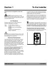
Electrical Connections
The QS series grills have one electrical connection.
Check the data plate on the g rill for voltage, cycle,
phase and electrical specifications. Refer to the
wiring diagram, provided inside the protective control
panel door at the front of the grill, for proper power
connections. The power connection is located inside
the grill behind the left side panel.
In the United States, this equipment is intended to
be installed in accordance with the National
Electrical Code (NEC), ANSI/NFPA 70-1987. The
purpose of the NEC code is the practical
safeguarding of persons and property from hazards
arising from the use of electricity. This code contains
provisions considered necessary for safety.
Compliance therewith and proper maintenance will
result in an installation essentially free from hazard!
In all other areas of the world, equipment should be
installed in accordance with the existing local codes.
Please contact your local authorities.
Stationary appliances which are not equipped with a
power cord and a plug or other device to disconnect
the appliance from the power source must have an
all-pole disconnecting device with a contact gap of at
least 3 mm installed in the external installation.
This equipment is provided with a grounding lug
that is to be properly attached to the rear of the frame
by the authorized installer. The installation location is
marked by the equipotential bonding symbol (5021 of
IEC 60417-1) on the removable panel and the frame.
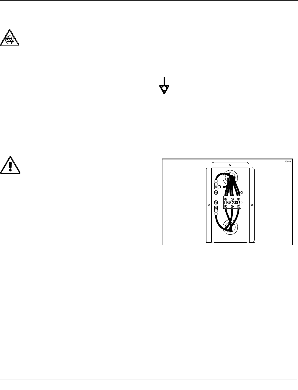
The proper wire size and fused circuit should be
selected according to grill data label information.
Incoming power must be connected to the terminals
with white characters on a black background.
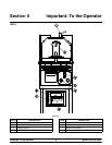
Figure 1