


Special offers from our partners!

Find Replacement BBQ Parts for 20,308 Models. Repair your BBQ today.

7
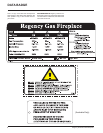
Regency IG35 Gas Inbuilt Fireplace
INSTALLATION
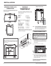
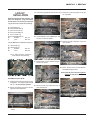
FLUEING
THE APPLIANCE MUST NOT BE CONNECTED
TO A CHIMNEY FLUE SERVING A SEPARATE
SOLID FUEL BURNING APPLIANCE.
This appliance is designed to attach to a 100
mm diameter twin skin or listed gas fuel type
fl ue liner running the full length of the chimney. A
minimum fl ue height of 1.5 m. is recommended.
The Regency Inbuilt Fireplace incorporates
its own internal draft diverter, so no additional
external draft diverter is required.
Periodically check that the fl ue is unrestricted
and an adequate draft is present when the unit
is in operation.
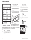
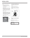
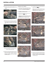
Before installing fl ue system ensure that the
damper plate is open and secure to prevent the
damper plate from falling down and crushing
the liner.
Install to AS5601-2004,(Australia) NZS 5261
(New Zealand).
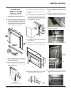
Combustion and Ventilation Air
WARNING: This appliance needs
fresh air for safe operation and must
be installed with provisions for ad-
equate combustion and ventilation
air available to the room in which it
is to be operating.
Air for combustion is drawn in through the front
of the unit, therefore, the front of the unit must
be kept clear of any obstructions.
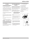
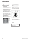
GAS PIPE PRESSURE
TESTING
The appliance must be isolated from the gas
supply piping system by closing its individual
manual shut-off valve during any pressure
testing of the gas supply piping system at
test pressures equal to or less than 1/2 psig.
(3.45 kPa). Disconnect piping from valve at
pressures over 3.45 kPa (14" w.c.).
The manifold pressure is controlled by a
regulator built into the gas control, and should
be checked at the pressure test point.
Note: To properly check gas pressure,
both inlet and manifold pressures
should be checked using the valve
pressure ports on the valve.
1) Make sure the valve is in the "OFF"
position.
2) Loosen the "IN" (# 3) and/or "OUT" (# 4)
pressure tap(s), turning counterclockwise
with a 1/8" wide fl at screwdriver.
3) Attach manometer to "IN" and/or "OUT"
pressure tap(s) using a 5/16" (8mm) ID
hose.
4) Seal and or check the pilot outlet (# 8)
5) The pressure check should be carried out
with the unit burning and the setting should
be within the limits specifi ed on the safety
label.
6) When fi nished reading manometer, turn
off the gas valve, disconnect the hose and
tighten the screw (clockwise) with a 1/8"
fl at screwdriver. Screw should be snug,
but do not over tighten.
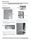
S.I.T. Valve Description
1) On-Off Solenoid Valve EV1
2) On-Off Solenoid Valve EV2
3) Inlet Pressure Test Point
4) Outlet Pressure Test Point
5) Connection for Pressure Regulator/
Combustion Chamber Compensation
6) Pressure Regulator for Minimum and
Maximum Outlet Pressure
7) Gas Outlet Pressure Electric Modulator
8) Pilot Outlet
9) Main Gas Outlet
10) Side Outlet