


Special offers from our partners!

Find Replacement BBQ Parts for 20,308 Models. Repair your BBQ today.

17
Regency IG35 Gas Inbuilt Fireplace
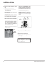
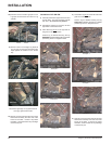
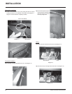
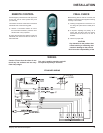
11) Place the cable ties thru the cable tie holders in the heat shield loosely
to secure loose wires.
Run the CAT5 cable from the unit thru the cable ties on the heat
shield and tighten cable ties. Ensure not to overtighten. Cut excess
cable tie. See diagram 8.
Diagram 8
CAT5 Cable
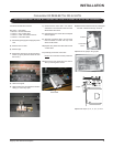
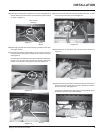
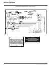
12) Partially mount the heat shield to the left side of the faceplace and
connect the CAT5 cable to the ECS manual control switch. See
diagram 9.
Diagram 9
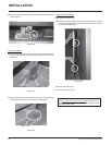
13) Secure the heat shield to the faceplate using 2 screws. See diagram
10. NOTE: Screws are secured from the front.
Diagram 10
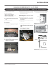
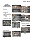
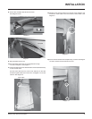
9) Bring faceplate close to unit.
10) Run thermodisc wires from top of heat defl ector through
left side of faceplate. See Diagram 7.
Diagram 7
Faceplate
8) Secure with 2 Phillips Head Screws as shown.
See Diagram 6 inset
Diagram 6
INSTALLATION