


Special offers from our partners!

Find Replacement BBQ Parts for 20,308 Models. Repair your BBQ today.
15
Regency IG35 Gas Inbuilt Fireplace
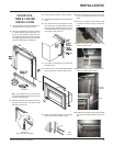
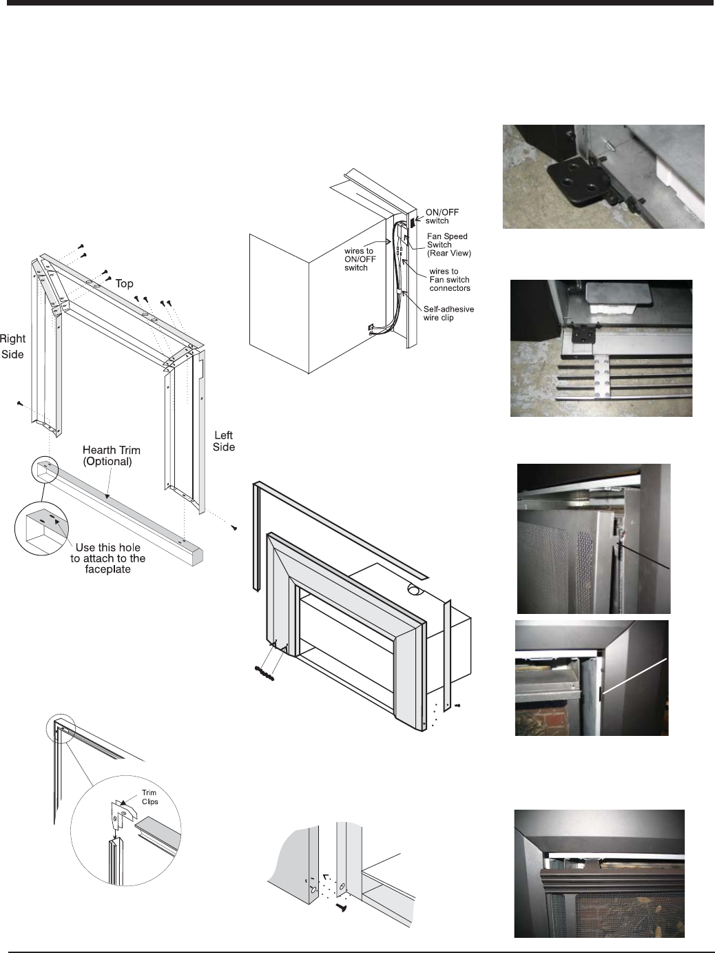
Diagram 1
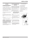
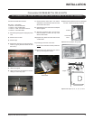
FACEPLATE,
TRIM & LOUVER
INSTALLATION
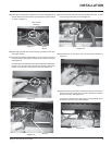
1) Lay the faceplate panels fl at, face down on
something soft so they don't scratch.
2) Take the top faceplate and align the holes
in it with the holes in the side panels. Us-
ing the screws provided, attach from the
top of the panel (the holes in the top panel
are slightly larger than the holes in the side
panel to facilitate easier installation).
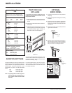
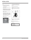
Diagram 2
Rear View: Trim Assembly
Hint: Don't tighten the trim to the bottom
of the faceplate side panels with the screws
provided. See diagram 1.
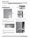
3) Using the connectors provided, join the left
side trim to the top trim. Connect the right
side trim to the top trim.
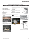
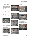
4) Connect the fan harness to the fan switch.
5) Connect the valve harness to the valve on/off
switch.
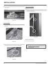
6) Tuck the wires into the faceplate to keep
them away from the inbuilt fi replace using
the clip provided. Attach the clip to the rear
of the faceplate to ensure that the wires do
not touch the side of the unit.
7) The power cord should be run behind the
faceplate panel.
8) Place the trim on the assembled faceplate
panels and secure it with the side screws.
Side
Screws
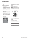
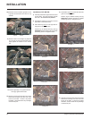
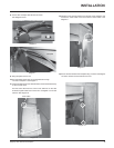
9) Attach the faceplate panels* to the inbuilt
fi replace body using 4 black screws.
10) Push the Regency logo plate into the two
holes in the bottom left corner of the face-
plate.
11) Place the 2 hinges for the bottom louver
in position and secure using 4 screws per
hinge.
12) Place the bottom louver in position and
secure it with 6 screws.
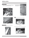
13) Install the safety screen by inserting the 4
screen brackets into the 4 slots.
14) Install the top louver by sliding the 2 bracket
clips into the brackets located on top of the
unit.
Screen
Bracket
Slots
INSTALLATION