


Special offers from our partners!

Find Replacement BBQ Parts for 20,308 Models. Repair your BBQ today.
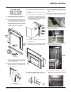
19
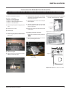
Regency IG35 Gas Inbuilt Fireplace
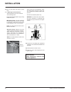
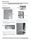
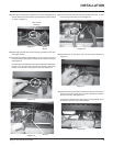
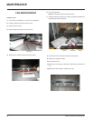
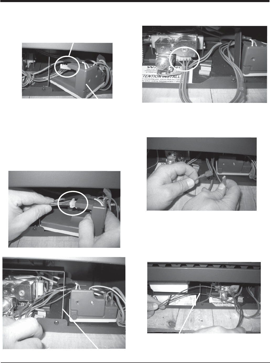
19) Carefully lift off the ignition module from the velcro and slightly bring
forward. Remove the wire harness connected to the ignition module
as shown in diagram 17.
Diagram 17
Ignition
Module
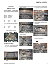
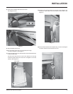
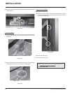
20) Discard the complete wire harness that was connected to the valve
and ignition module.
Wire Harness
Removed
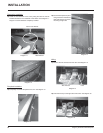
21) Take the wire harness included with the kit and connect one end of
the wire harness to the ignition module (in place of the one removed),
see diagram 18 .
Place the ignition module back on the velcro at the base of the fi rebox.
Ensure to run the loose wires from the wire harness in behind the
bracket on the left side of the ignition module. See diagram 19.
Diagram 18
Diagram 19
Bracket
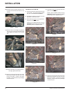
22) Connect the other end of the new wire harness to the valve, in place
of the one removed in step 16. See diagram 20.
Diagram 20
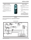
23) Disconnect the red split wires from the wire harness as shown in
diagram 21.
Diagram 21
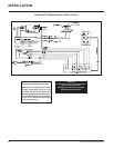
24) Feed the remaining thermodisc wires thru the opening on the bottom
of the left side of the fi rebox and run them in behind the bracket to
the left of the valve. See diagram 22.
Connect the 2 wires from the thermodisc to the appropriate wire on
the harness; female to male, male to female.
Diagram 22
Bracket
INSTALLATION