


Special offers from our partners!

Find Replacement BBQ Parts for 20,308 Models. Repair your BBQ today.
16
Regency IG35 Gas Inbuilt Fireplace
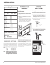
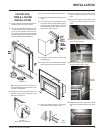
PREMIUM FLUSH FRONT INSTALLATION
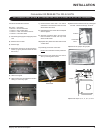
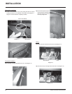
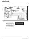
6) Place the ECS manual control switch key pad on the outside of the
opening in the faceplate and the control switch to the inside of the
faceplate.
Align the holes and secure in place using the 2 bolts, washers,
phenolic spacers, split lock washers and nuts. See diagram 3 for
sequence. Diagram 4 shows ECS manual control switch mounted
on faceplate.
ECS Manual Switch
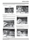
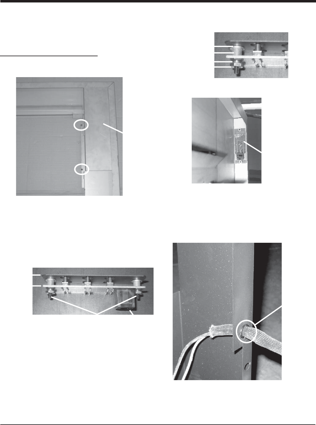
7) Run the thermodisc wires thru the hole in the heat shield.
Then place the grommet over the sleeve and tuck into the hole in the
heat shield as shown in diagram 5.
Grommet
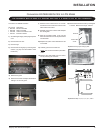
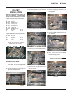
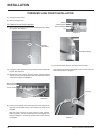
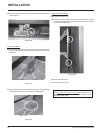
1) Unplug the power source.
2) Remove the glass door.
Left Side
Heat Shield
Diagram 1
Diagram 5
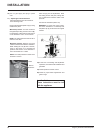
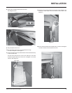
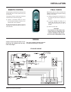
4) Unplug the CAT5 cable from the ECS manual switch included with
the unit. See diagram 2.
5) Remove the 2 bolts, washers, phenolic spacers, split lock washers
and nuts securing the manual control switch to separate the manual
control switch keypad. See diagram 2.
Manual Control
Switch Keypad
Bolts
Diagram 2
Phenolic Spacer
Washer
Split Lock Washer
Nut
Diagram 3
Diagram 4
ECS Manual Control Switch Installation:
3) Remove the heat shield from the left side of the faceplate by undoing
the 2 screws. See diagram 1.
Control Switch
CAT5 Cable
Receptacle
INSTALLATION