


Special offers from our partners!

Find Replacement BBQ Parts for 20,308 Models. Repair your BBQ today.

9
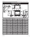
LDVR Series Direct Vent Gas Fireplace
10007317
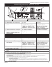
The fireplace, when installed, must be
electrically connected and grounded in
accordance with local codes or, in the ab-
sence of local codes, with the current CSA
C22.1 Canadian Electrical Code.
For USA installations follow local codes
and the national electrical code ANSI/
NFPA No. 70.
It is strongly suggested that the wiring of
the EB-1 Electrical Junction Box be carried
out by a licensed electrician.
Ensure that the power to the supply line
has been disconnected before commenc-
ing this procedure.
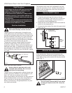
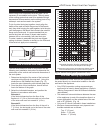
The EB-1 Electrical junction box has been fitted stand
-
ard on this model to allow for the easy connection of an
optional fan kit.
To connect the EB-1 box to the house electrical supply
follow the steps below.
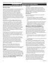
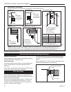
1. Unscrew the retaining screw from the EB-1 base
plate and remove the EB-1 assembly from the
appliance. (Fig. 8)
2. Remove the front cover of the EB-1 box.
3. Remove the plug socket assembly from the EB-1
box.
4. Feed the supply line in through the EB-1 opening in
the side of the appliance and then through the back
of the EB-1 assembly. (Fig. 8)
5. Connect the black wire of the power supply line to
the brass screw (polarized) of the socket assembly.
6. Connect the white wire of the power line to the
chrome screw of the socket assembly.
7. Connect the ground wire of the supply line to the
green screw of the socket assembly.
8. Refit the socket assembly back into the electrical
box and replace the cover plate. Secure the cable
with the clamp on the outside of the EB-1 base
plate and refit the EB-1 assembly to the unit with the
screw removed in step 1.
This appliance may be fitted with a Synetek ignition
module.
Installation of the remote on/off starter switch or
wall thermostat on electronic ignition units.
1. Thread the wiring through the holes on the side
panels of the appliance. Take care not to cut the wire
or insulation on metal edges. Route the wire to a
conveniently located receptacle box.
2. Attach the wire to the ON/OFF switch and install the
switch into the receptacle box.
3. Connect the white wire from the wall switch or wall
thermostat to the white wire terminal from the elec-
tronic module. Connect the black wire from the wall
switch or the red wire from the wall thermostat, to
the red wire terminal from the electronic module.
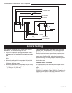
Electronic Gas Control Valve
EB-1 Electrical Box
FP580
INSTA VENT FREE
EB1 JUNCTION BOX
11/18/97
OUTSIDE
INSIDE
BACK OF UNIT
FP580
Electrical Box
Retaining Screw
Fig. 8 EB-1 receptacle.