


Special offers from our partners!

Find Replacement BBQ Parts for 20,308 Models. Repair your BBQ today.

15
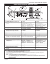
LDVR Series Direct Vent Gas Fireplace
10007317
CFM133
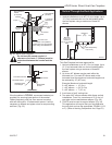
DVR Series Typical corner install
2/26/01 sta
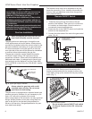
Zero
Clearance
Sleev
e
Firestop
CFM133
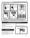
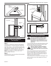
Fig. 17 Firestop and zero clearance sleeve in place.
FP1005
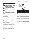
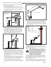
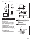
Side View Vent Termination
1/25/00 djt
Finished Wall
Vent Termi
-
nation
FP1005
Fig. 18 Side view of final unit location.
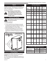
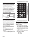
Vertical Sidewall Applications
Since it is very important that the vent-
ing system maintain its balance between
the combustion air intake and the flue
gas exhaust, certain limitations as to vent
configurations apply and must be strictly
adhered to.
The Vent Graph shows the relationship between vertical
and horizontal side wall venting and will help to deter-
mine the various dimensions allowable.
Minimum clearance between vent pipes
and combustible materials is 1”(25 mm)
on top, bottom and sides unless otherwise
noted.
When vent termination exits through foundations less
than 20” below siding outcrop, the vent pipe must
flush up with the siding. It is always best to locate the
fireplace in such a way that minimizes the number of
offsets and horizontal vent length.
The horizontal vent run refers to the total length of vent
pipe from the flue collar of the fireplace to the face of
the outer wall.
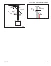
Rear Wall Vent Installations -
Flex Vent Pipe
Follow Steps 1 and 2 on Page 13.
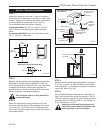
Step 3
Install the 4” (102mm) flex vent pipe to the appliance
collars described in “General Information Assembling
Vent Pipes”, Page 11. If the installation requires a 45°
angle, grasp the vent pipe close to the appliance collar
and bend to 45°. DO NOT exceed 45°. (Fig. 19)
Install the 7” vent pipe in the same manner as Step 2.
NOTE: There must be a 1” (25 mm) rise in a 24”
(610mm) length of flex vent.
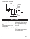
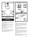
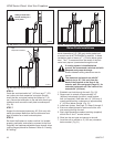
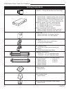
Step 4
Assemble the flex vent to the collars on the termination
as you did on the appliance.
FP1473
corner flex install
4/04 djt
Termination
Flex Section
Appliance Collars
FP1473
Fig. 19 Grasp the vent pipe close to the collar and bend to
45° angle. Do not exceed 45°.
FP1472
rise in length
4/04 djt
FP1472
Fig. 20 There must be a 1/2” rise per foot length.
Rise