


Special offers from our partners!

Find Replacement BBQ Parts for 20,308 Models. Repair your BBQ today.

33
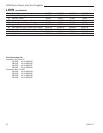
LDVR Series Direct Vent Gas Fireplace
10007317
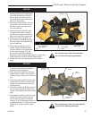
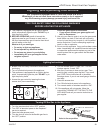
Burner and Burner Compartment
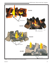
It is important to keep the burner and the burner
compartment clean. At least once per year the logs and
lava rock/ember material should be removed and the
burner compartment vacuumed and wiped out. Remove
and refit the logs as per the instructions in this manual.
Always handle the logs with care as they
are fragile and may also be hot if the
fireplace has been in use.
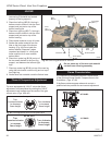
FK24/FK12 Fan Assembly
The fan unit requires periodic cleaning. At least once
per month in the operating season open the lower
louvre panels and wipe or vacuum the area around the
fan to remove any build up of dust or lint.
Brass Trim
Clean the brass trim pieces using a soft cloth lightly
dampened with lemon oil. Do not use water or
household cleaners on any brass components.
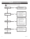
Cleaning the Standing
Pilot Control System
The burner and control system consist of:
• burner • gas orifice
• pilot assembly • thermopile
• millivolt gas valve
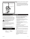
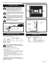
Maintenance
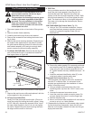
12. After bleeding the gas line and checking for leaks
with a soap solution, replace the window frame
assembly. Fire up the unit, check for flame impinge-
ment on the logs, adjusting them if necessary. Check
the manifold and supply pressures against the appli-
ance specifications.
Most of these components may require only an
occasional checkup and cleaning and some may
require adjustment. If repair is necessary, it should
be performed by a qualified technician.
1. Turn off pilot light at gas valve.
2. Allow fireplace to cool if it has been operating.
3. Remove window frame assembly. (Refer to Window
Frame Assembly Removal section.)
4. Remove logs.
5. Vacuum burner compartment especially around
orifice primary air openings.
6. Visually inspect pilot. Brush or blow away any dust
or lint accumulation.
7. Reinstall logs.
8. Ignite pilot - Refer to Lighting Instructions.
9. Reinstall window frame assembly.
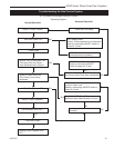
To obtain proper operation, it is imperative that the pilot
and burner’s flame characteristics are steady, not lifting
or floating.
Typically, the top 3/8” to 1/2” of the thermopile should
be engulfed in the pilot flame. (Refer to Page 25, Figure
47)
To adjust pilot burner: (by qualified service technician)
1. Remove pilot adjustment cap
2. Adjust pilot screw to provide properly sized flame.
3. Replace pilot adjustment cap.
The primary air shutter is set at factory and should
only be adjusted, if necessary, by a qualified service
technician.
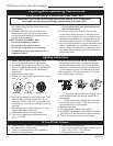
L
O
HV120
Honeywell valve
conversion
9/24/02 djt
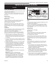
Regulator Cap
Conversion Screw
Pressure Regulator
Housing
HV120
Fig. 51 Honeywell Gas Valve.