


Special offers from our partners!

Find Replacement BBQ Parts for 20,308 Models. Repair your BBQ today.

14
LDVR Series Direct Vent Gas Fireplace
10007317
DVR584-600
Rear vent no elbows
2/99 djt
20"
(508mm)
Top View
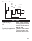
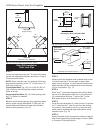
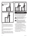
Straight Venting
FP836
Rear Vent-Top View
11/21/98
20"
(508mm)
Max.
REAR VENT-TOP VIEW
20"
(508mm)
Max.
Top View
Rear Vent Corner Installation
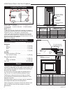
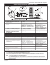
Fig. 14 Rear vent applications, one 45° elbow.
45°
45°
Rear Wall Installation
Twist Lock Pipe
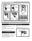
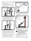
STEP 1
Locate vent opening on the wall. To locate hole center
consult with appropriate fireplace dimensions, Page 4.
Frame as shown below.
NOTE: When using flex vent, the opening will have to
be measured according to the 1/2” (13 mm) rise in 12”
(305 mm) vertical run.
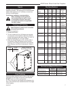
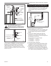
Combustible Walls
(Fig. 15): Cut a 10³⁄₈”H x 9³⁄₈” W
(264 x 240 mm) hole through the exterior wall and
frame as shown.
Noncombustible Walls
(Fig. 15): Hole opening must
be 7¹⁄₂” (190mm) in diameter.
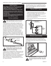
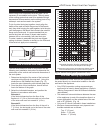
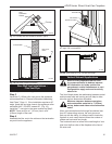
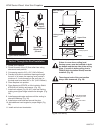
STEP 2
Measure wall thickness and cut zero clearance sleeve
parts to proper length (MAXIMUM 12”/305 mm). As-
semble sleeve and attach to firestop with #8 sheet
metal screws (supplied). (Fig. 16)
VO584-100
Vent Opening
2/99 djt
Vent Opening for Combustible Wall
9³⁄₈”
(240mm)
10³⁄₈”
(264mm)
Fireplace Hearth
Framing
Detail
Opening for Noncombustible Wall
7¹⁄₂”
(190mm)
VO584-100
Fig. 15 Locate vent opening on wall.
ZCS101
Zero Clearance Sleeve
3/11/99 djt
Max. Length
12” (305mm)
#8 Screws (2)
#8 Screws
(2)
Adjustable
Zero Clearance
Sleeve
#8
Screws
(2)
Adjustable Zero Clearance Sleeve
ZCS101
Fig. 16 Adjustable zero clearance sleeve.
Firestop
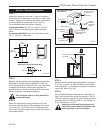
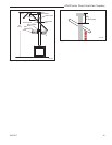
STEP 3
Measure from the fireplace collar or elbow face to face
of outside wall (add 2” for vent pipe overlap). Mark
pipes and cut to length. It is very important that the two
pipes are flush with the outside wall once the fireplace
is in its final location. (Fig. 17)
STEP 4
Slip 4” and 7” pipes onto respective flue collars. Make
sure to fix to the fireplace collar the 4” pipe with three
(3) screws before fixing the 7” pipe on the 7” collar.
Both pipes must be on a level plane. (Fig 18)
STEP 5
Guide the vent termination 4” collar into the 4” pipe then
the 7” collar into the 7” pipe. Do not force the venting
into position. If the pipes do not line up with the termi-
nation collars, disassemble pipes and reattach to the
fireplace collar. (Fig. 18)
STEP 6
Secure fireplace to floor through floor holes and adjust-
able frame drywall strip (nailing flange) to frame. (Refer
to Framing & Finishing Section).