


Special offers from our partners!

Find Replacement BBQ Parts for 20,308 Models. Repair your BBQ today.

12
LDVR Series Direct Vent Gas Fireplace
10007317
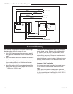
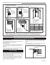
General Information Assembling Vent Pipes
Canadian Installations:
Venting system must be installed in accordance with the
current CSA-B149.1 installation code.
USA Installations:
The venting system must conform with local codes and/
or the current National Fuel Gas code ANSI Z223.1/
NFPA 54.
Only venting components manufactured by CFM Corpo
-
ration can be used in Direct Vent systems.
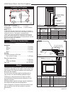
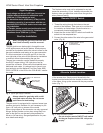
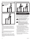
Flex Vent Pipes
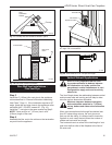
Before joining the flex vent pipe to the unit, apply a
bead of high temperature sealant* (provided) to the 4”
pipe exiting the fireplace. Secure flex vent piep in place
with a hose clamp (provided).
*Be sure the flex pipe overlaps at least 1” (25mm) onto
the collars of the fireplace and termination. If the ter
-
mination has an internal bead, be sure to overlap and
secure 1” (25mm) past the bead.
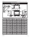
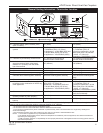
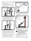
Fig. 10a Termination clearances.
* Be sure the vent is actually crushed before proceed-
ing. Apply a tug to be sure the vent will not slip off the
collars.
Repeat process with 7” flex vent pipe. The same proce-
dure must be performed on the vent side.
FP1471
flex vent
Apply High Temperature
Sealant
Hose Clamp
FP1471
Fig. 11 Apply high temperature sealant to 4” and 7” pipes.
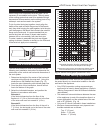
Outside Corner
Inside Corner
Termination Clearances
Termination clearances for buildings with combustible and noncombustible exteriors.
G =
Combustible
6" (152 mm)
Noncombustible
2" (51 mm)
F =
Combustible
6" (152 mm)
Noncombustible
2" (51 mm)
G
Balcony -
with no side wall
M =
Combustible &
Noncombustible
12" (305 mm)
M
Balcony -
with perpendicular side wall
M = 24" (610 mm)
P = 20” (508 mm)
M
F
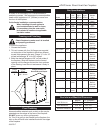
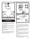
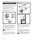
Alcove Applications*
C
D
C
E
V
V
Combustible &
Noncombustible
V
V
V
E = Min. 6” (152 mm) for
non-vinyl sidewalls
Min. 12” (305 mm) for
vinyl sidewalls
O = 8’ (2.4 m) Min.
O
P
584-15
No.
of Caps D
Min.
C
Max.
1 3’ (914 mm) 2 x D
Actual
2 6’ (1.8 m) 1 x D
Actual
3 9’ (2.7 m) 2/3 x D
Actual
4 12’ (3.7 m) 1/2 x D
Actual
D
Min.
= # of Termination caps x 3
C
Max.
= (2 / # termination caps) x D
Actual
*NOTE: Termination in an alcove space (spaces open only on one side and with an overhang) is permitted with the dimensions
specified for vinyl or non-vinyl siding and soffits. 1. There must be a 3’ (914 mm) minimum between termination caps. 2. All
mechanical air intakes within 10’ (1 m) of a termination cap must be a minimum of 3’ (914 mm) below the termination cap. 3. All
gravity air intakes within 3’ (914 mm) of a termination cap must be a minimum of 1’ (305 mm) below the termination cap.