


Special offers from our partners!

Find Replacement BBQ Parts for 20,308 Models. Repair your BBQ today.

26
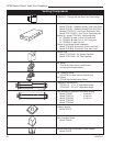
LDVR Series Direct Vent Gas Fireplace
10007317
43LDVR
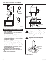
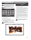
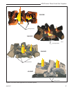
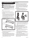
1. Place rear log (BD15) on rear bracket
(ensure log is centered and seated
properly to the log support).
2. Place front left log (BD16). Use log’s
bottom notch to locate it onto the front
support and just rest on top of the
burner housing tile.
3. Place front right log (BD17). Use log’s
bottom notch to locate it onto the front
support and just rest on top of the
burner housing.
4. Place ember material on top of burner.
5. Scatter the ember material over the
tiles on the front area of the burner
housing. (Fig. 44) Do not pack the
ember material. Separate it when
unpacked and keep it in a fluffy and
loose condition for a more realistic
ember effect.
6. Place front center log (B138) on top of
the two small shelves at the front log
support, and between the left and right
logs.
7. Place top center log (BD18) on top of the rear log
using the hole locator under the log and on top of
front right log.
8. Scatter lava rock material round the firebox base.
Rear
(BD15)
Top Center
(BBD18)
Front Right
(BD17)
Front
Left
(BD16)
Lava Rock
Front Center
(B138)
Ember Material
Lava
Rock
LG434
Fig. 44 Correct log placement for 43LDVR.
Do not place any of the lava rock material
on the burner housing assembly.
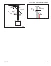
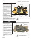
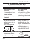
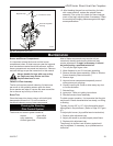
RN/RP & EN/EP Models
For units equipped with “HI/LO” valves the flame
adjustment is accomplished by rotating the “HI/LO”
adjustment knob located near the center of the gas
control valve. (Figs. 45 & 46)
Flame & Temperature Adjustment
Turn
counterclockwise
to decrease
flame height
Turn clockwise
to increase
flame height
HV102
Honeywell hi/lo knob
4/5/99 djt
Fig. 45 Flame adjustment knob for Honeywell valve.
Honeywell Valve
It is important to periodically perform a visual check
of the pilot and burner flames. Compare them to the
illustrations. (Figs. 47-48)
If the flame patterns appear abnormal contact a
qualified service provider for service and adjustment.
Flame Characteristics
L
O
H
I
FP390
FLAME ADJUSTMENT KNOB
11/21/96
Turn
counterclockwise
to increase
flame height
Turn clockwise
to decrease
flame height
SIT 820 Valve
Fig. 46 Flame adjustment knob for SIT valve.
SIT RN/RP
SIT EN/EP
FP1541
Fig. 47 Correct pilot flame appearance.