


Special offers from our partners!

Find Replacement BBQ Parts for 20,308 Models. Repair your BBQ today.

6
LDVR Series Direct Vent Gas Fireplace
10007317
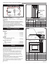
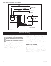
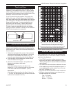
A) Flat on wall B) Cross corner C) **Island
D) *Room divider E) *Flat on wall corner F) Chase installation
Y) 6” minimum
NOTE: (Fig. 2)
** Island (C) and Room Divider (D) installation is possible as
long as the horizontal portion of the vent system (X) does not
exceed 20’ (610cm). See details in Venting Section.
* When you install your fireplace in(D) Room divider or (E)
Flat on wall corner positions (Y), a minimum of 6” (153mm)
clearance must be maintained from the perpendicular wall and
the front side edge of the fireplace.
Refer to (Y) in Figure 2.
Locating Your Fireplace
Y
E
A
B
C
D
F
Y
B
X
LU584-R
Locating unit
2/23/01 sta
X
Fig. 2 Locate gas fireplace.
LU584-R
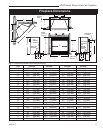
Top of Unit to Ceiling ............................... 36” (914 mm)
Appliance
Top ..........................................................
0” (0 mm)
Bottom .....................................................
0” (0 mm)
Side .........................................................
0” (0 mm)
Back ........................................................
0” (0 mm)
Venting
Concentric sections of DV Vent
Top, bottom & sides ..............................
1” (25 mm)
Rear Vent Applications:
Top ........................................................
2” (50 mm)
Sides and Bottom ..................................
1” (25 mm)
Flex Vent ..................................................
7/8” (22 mm)
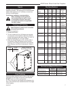
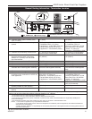
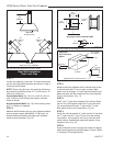
Mantels
The height that a combustible mantel is fitted above the
fireplace is dependent on the depth of the mantel. This
also applies to the distance between the mantel leg (if
fitted) and the fireplace.
For the correct mounting height and widths refer to
Figs. 3a and 3b, and the following Mantel Charts.
The fitting of a bay window trim kit does not effect
the distances and reference points referred to in the
diagram and chart.
Noncombustible mantels and legs may be installed at
any height and width around the appliance.
When using paint or lacquer to finish the mantel, such
paint or lacquer must be heat resistant to prevent
discoloration.
Clearance to Combustibles
CFM146
A B C
D
E
V
W
X
Y
Z
Fireplace
CFM146
DV Mantel Chart
7/5/01 sta
Top Louvre
Assembly
Top of Combustion
Chamber
Mantel Chart
Mantel Shelf Mantel from Top
Ref. or Breast Plate Ref. of Combustion Chamber
Depth 36/39/43 LDVR 33LDVR
V 10” (254 mm) A 17” (432 mm) 16
¹⁄₂” (419 mm)
W 8” (203 mm) B 15” (381 mm) 14
¹⁄₂” (368 mm)
X 6” (152 mm) C 13” (330 mm) 12¹⁄₂” (318 mm)
Y 4” (102 mm) D 11” (279 mm) 10¹⁄₂” (267 mm)
Z 2” (51 mm) E 9” (229 mm) 8
¹⁄₂” (216 mm)
Fig. 3a Combustible mantel minimum installation.
3/4” (19 mm) Scribe
Moulding for use with
CFM Cabinets
CFM170
J
F
G
H
I
Mantel
Leg
CFM164a
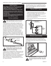
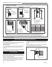
Mantel Leg Chart
06/22/01 sta
Black
Surround
Face
CFM170
DV Builder Front
View
O
N
M
L
K
Side of
Combustion Chamber
CFM164a
Mantel Mantel Leg FromSide
Ref. Leg Depth Ref. of Comb. Opening
F 10” (254 mm) K 11¹⁄₂” (292 mm)
G 8” (203 mm) L 9¹⁄₂” (241 mm)
H 6” (152 mm) M 7¹⁄₂” (191 mm)
I 4” (102 mm) N 5¹⁄₂” (140 mm)
J 2” (51 mm) O 3¹⁄₂” (89 mm)
Fig. 3b Combustible mantel leg minimum installation.
3/4” (19 mm) Scribe
Moulding for use with
CFM Cabinets