


Special offers from our partners!

Find Replacement BBQ Parts for 20,308 Models. Repair your BBQ today.
10
LDVR Series Direct Vent Gas Fireplace
10007317
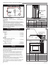
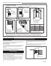
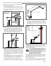
Your fireplace is approved to be vented either through
the side wall, or vertically through the roof.
• Only CFM Corporation venting components specifi-
cally approved and labelled for this fireplace may be
used.
• Vent terminations shall not be recessed into a wall or
siding.
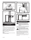
• Horizontal venting which incorporates the twist lock
pipe must be installed on a level plane without an
inclining or declining slope.
• Horizontal venting which incorporates the use of flex
venting shall have an inclining slope from the unit of
1” (25 mm) per 24” (610 mm).
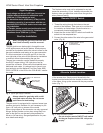
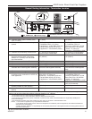
General Venting
There must not be any obstruction such as bushes,
garden sheds, fences, decks or utility buildings within
24” (610mm) from the front of the termination hood.
Do not locate termination hood where excessive snow
or ice build up may occur. Be sure to check vent termi-
nation area after snow falls, and clear to prevent ac-
cidental blockage of venting system. When using snow
blowers, make sure snow is not directed towards vent
termination area.
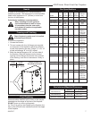
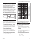
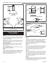
Location of Vent Termination
It is imperative the vent termination be located observ-
ing the minimum clearances as shown on the next
page.
*Check with local codes or in absence of same with
CSAB149.1 Installation Codes (1991) for Canada or fol-
low the current National Fuel Gas Code, ANSI Z223.1/
NFPA 54 for installations in the USA.
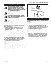
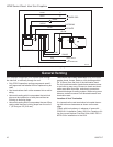
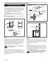
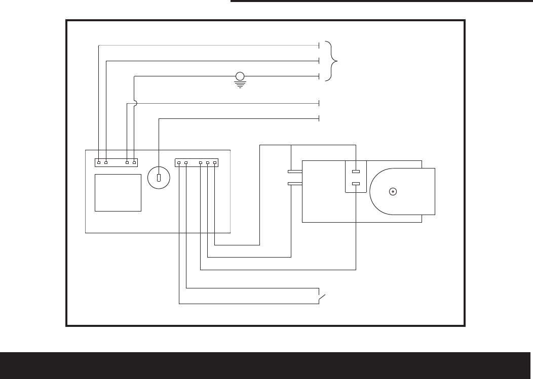
POWER CORD
CIRCUIT BOARD
ON/OFF SWITCH
OR
WALL THERMOSTAT
VALVE
RED
WHITE
BLUE
YELLOW
PURPLE
BLACK
WHITE
GREEN
PILOT SENSING
PILOT IGNITER
ORANGE
L1
L2
M
O
P
O
FP1571
SIT822
Synetek wiring
4/05
CLEAR
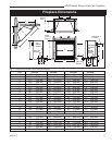
Fig. 9 SIT822 Valve with Synetek electronic control wiring diagram.
FP1571