


Special offers from our partners!

Find Replacement BBQ Parts for 20,308 Models. Repair your BBQ today.

32
LDVR Series Direct Vent Gas Fireplace
10007317
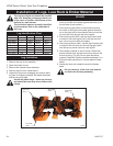
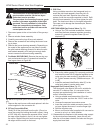
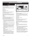
The conversion of this appliance from one
gas to another must be carried out by an
authorized service provider.
1. Disconnect power to the unit and shut off the gas sup
-
ply.
2. Remove window frame assembly.
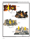
3. Carefully remove the logs & lava rock material.
4. Remove the screws that are holding the burner hous-
ing in place.
5. Remove the burner housing assembly. Depending on
the model of the appliance you may have to loosen
the pilot bracket retaining screw/nut to allow the pilot
and bracket assembly to tilt and give enough clear-
ance to remove the burner housing assembly.
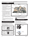
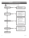
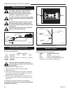
6. For Model 36LDVR ONLY: Remove the rear log sup-
port and relocate the two (2) screws that locate the
rear log as shown in Figure 49.
Fuel Conversion Instructions
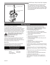
9. PSE Pilot
Using a suitable wrench on the hexagonal body un-
screw the pilot hood assembly from the pilot, do
not twist the hood itself. Remove the orifice and
replace it with the new orifice supplied in the kit. Refit
the pilot hood assembly. Do not over-tighten the pilot
hood. The hood must return to its original alignment.
Take care not to damage the thermocouple, thermo-
pile or igniter.
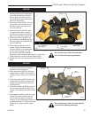
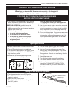
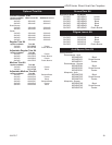
10.SIT 820 NOVA Gas Control Valve (Fig. 50)
a. Using a Torx T20 or slotted screwdriver, remove
and save the three pressure regulator mounting
screws (A), pressure regulator tower (B) and
diaphram (C).
The procedure for converting from one gas to
another is the same regardless of the initial
gas used. The only variation is in the orifice
sizes and component part numbers. Your
authorized service provider will ensure the
correct parts are used.
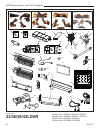
Fig. 50 Nova SIT820 Gas Valve.
D
E
F
FC108
SIT
regulator
conversion
10/03
O
F
F
P
I
L
O
T
O
FC107
SIT820
valve conversion
10/03
A
B
C
O
F
F
P
I
L
O
T
O
FC107/108
Natural Gas
Log Locator
Pin
Propane Gas
Log Locator
Pin
KT615
Fig. 49 Move log locator pins to new locations on rear log sup-
port.
b. Ensure the rubber gasket (D) is properly positioned
and install the new HI/LO pressure regulator to the
valve using the new screws (E) supplied with the
kit. Tighten screws securely. (Reference torque - 25
in.LB)
c. Install the enclosed identification label (F) to the
valve body where it can be easily seen.
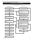
Honeywell Gas Control Valve (Fig. 51)
The Honeywell valve fitted to this unit is suitable for
use with LP or Natural Gas. It is converted to the
required gas application by the installation of a color
coded “conversion screw”.
a. Using a suitable small screwdriver lift out the
central regulator cap from the “HI/LO” knob on the
valve.
b. Unscrew the exposed conversion screw.
c. Insert the new color coded conversion screw. Do
not over-tighten the screw, it must be finger tight.
d. Refit the regulator cap.
e. Mount conversion label supplied with conversion
screw to valve in a visible position.
11. Reassemble the fireplace in the reverse order, except
for the window frame assembly. Leave this off until
after the unit has been checked for leaks and the gas
supply has been bled.
7. Remove the main burner orifice and replace it with the
orifice supplied in the conversion kit.
8. SIT top Convertible Pilot
Gently lift off the pilot hood from the pilot. (Do not re
-
move the spring clip holding the hood in place). Using
a 5/32” Allen key, unscrew the exposed orifice. Insert
the new orifice supplied in the kit, do not over tighten
the orifice. Replace the pilot hood ensuring the index
tab aligns with the notch on the hood.