


Special offers from our partners!

Find Replacement BBQ Parts for 20,308 Models. Repair your BBQ today.

17
LDVR Series Direct Vent Gas Fireplace
10007317
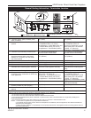
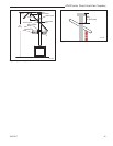
Vertical Sidewall Installation
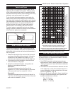
STEP 1
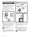
Locate vent opening on the wall. It may be necessary
to first position the fireplace and measure to obtain hole
location. Depending on whether the wall is combustible
or noncombustible, cut opening to size. (Fig. 25)
For combustible walls first frame in opening.
Combustible Walls (Fig. 25): Cut a 9³⁄₈”H x 9³⁄₈” W
(240 x 240 mm) hole through the exterior wall and
frame.
Noncombustible Walls
(Fig. 25): Hole opening must
be 7.5” (190 mm) in diameter.
VO584-100
Vent Opening
2/99 djt
Vent Opening for Combustible Wall
9³⁄₈”
(240mm)
9³⁄₈”
(240mm)
Fireplace Hearth
Framing Detail
Opening for Noncombustible Wall
7¹⁄₂”
(190mm)
VO584-100
Fig. 25 Locate vent opening on wall.
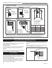
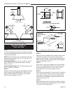
STEP 2
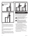
Measure wall thickness and cut adjustable zero clearance
sleeve parts to proper length (MAXIMUM 12”/305 mm).
(Fig. 26) Adjust sleeve to minimum (9³⁄₈” x 9³⁄₈” and attach
to firestop with #8 sheet metal screws (supplied). As-
semble sleeve and attach to firestop with #8 sheet metal
screws (supplied). Install firestop assembly.
Zero clearance sleeve is only required for
combustible walls.
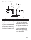
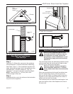
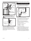
STEP 3
Attach the appropriate venting component(s) to the
inner and outer flue collars of the fireplace using three
(3) screws. (Fig. 27) Follow with the installation of the
inner and outer elbow. Again secure joints with three (3)
sheet metal screws.
CFM135
Zero Clearance Sleeve
2/26/01 sta
Adjustable Zero Clear-
ance Sleeve
Maximum Length
12” (305mm)
#8 Screws (2)
Adjust-
able Zero
Clearance
Sleeve
Firestop
#8 Screws
(2)
Wall Exterior
Wood Framing
Firestop
Vent Pipe
Drywall
Zero Clearance
Sleeve Flush with
Wall Exterior
CFM135
Fig. 26 Locate vent opening on wall.
#8 Screws (2)
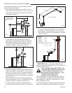
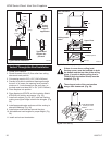
STEP 4
Measure the horizontal length requirement including a
2” (51 mm) overlap, i.e. from the elbow to the outside
wall finish plus 2”, or the distance required if installing a
second 90° elbow. (Fig. 28)
STEP 5
Use appropriate length of pipe section - telescopic or
fixed - and install the horizontal vent sections. The 20”
(508 mm) section of pipe which goes through the wall is
packaged with the 7TDVSK starter kit, and can be cut
to suit if necessary. (Fig. 29)
Sealing vent pipe and firestop gaps with
high temperature sealant will restrict cold
air being drawn in around fireplace.
CFM143
2/2/01 sta
Ensure Pipes are
Concentric
CFM143
Fig. 27 Apply sealant to inner and outer pipe.